
From temperature measurement to verifiable device data

How to choose a temperature sensor and integrate it into a device

A temperature sensor converts an electrical property that changes with temperature into measurable data. Selection is not based on measurement range alone: measuring air, a surface or a liquid requires different arrangements. NTC, RTD, thermocouple and digital sensor options must be considered alongside response time, connections, measurement uncertainty and maintenance needs. VOMRO develops sensor reading electronics, embedded software and mechanical integration for customer devices according to project requirements.

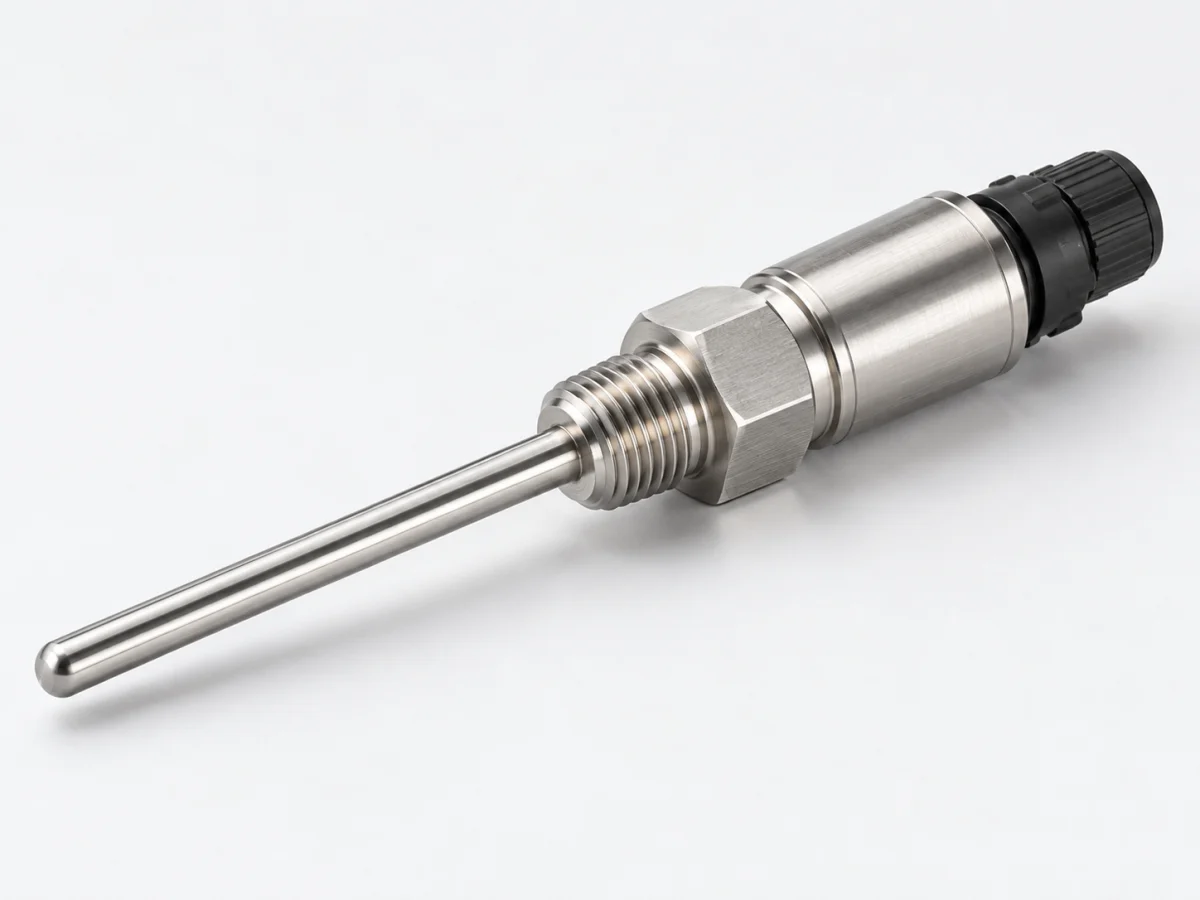
Finished temperature sensor probe with a sealed stainless steel body, threaded process connection and connector
Illustrative sensor product image.
Measured quantityTemperature, together with the measurement location
Main optionsNTC, RTD, thermocouple and IC
Acceptance criterionRange, total error and response time

VOMRO engineering approach

First determine where measurement is needed and how quickly it must respond.

The temperature of a board inside a control cabinet is not the same as that of the air entering the cabinet. Similarly, a probe immersed in liquid may not represent every point in a tank. Defining the measured medium, probe location and the control decision that will use the result comes before selecting a more expensive sensor.

For example, monitoring a door opening in a refrigerated device and recording the temperature change of the product mass are different requirements. The first captures rapid air changes; the second reflects a different thermal time response. The expected behaviour must be stated clearly in the acceptance test.

The complete measurement process

From sensed quantity to usable data

  1. 01Temperature and thermal contact
  2. 02RTD, NTC or digital sensor
  3. 03Measurement circuit and corrections
  4. 04Unit, time and validity

Conceptual diagram. The actual measurement range, error budget and validation plan are defined for the application.

01

What changes with NTCs, RTDs, thermocouples and digital sensors?

NTC thermistors and RTDs are read through resistance changes with temperature; thermocouples use the voltage produced by a temperature difference between dissimilar metals. Integrated circuit sensors can provide an analogue voltage or digital data. These options cannot connect directly to the same input circuit; excitation, amplification, reference and conversion approaches are selected together with the sensor.

TI recommends assessing total error, power and cost across the temperature measurement chain, rather than considering the sensing element alone. When comparing project options, we therefore include cables, connectors, analogue circuitry, software conversion and production testing alongside the sensor price. This makes the additional system work associated with an easily sourced component visible.

02

How do accuracy, resolution and repeatability differ?

Showing more decimal places does not mean the measurement is closer to the reference temperature. Resolution describes the distinguishable step, accuracy the closeness to a reference, and repeatability the closeness of results under the same conditions. In a quotation, we define these as separate acceptance criteria over the intended operating range instead of combining them into one number.

Distinguish the normal operating range from short-term exposure in the requirements list. Specify the delay permitted by the control loop, the logging interval and the point at which an alarm decision is made. If every part of the range does not need the same precision, identifying the critical range allows more realistic comparison of candidate architectures.

03

How do the probe, board and enclosure affect measurement?

Heat from a regulator, processor or display can bias a sensor intended to measure ambient air. Sensirion's design guide considers separation from heat sources alongside appropriate air exchange with the environment. Successful results on an open board therefore do not by themselves represent performance inside an enclosed housing.

On the prototype, we compare the intended sensor location with alternatives. We record separately with fans on and off, during heavy communication and at idle. For surface measurements, the attachment method is included in the project drawing; for liquid probes, position, immersion and sealing requirements are included. After mechanical changes, we reassess whether earlier results remain valid.

04

What integration work does a custom circuit board involve?

For analogue sensors, the input range, ADC selection and signal settling time before conversion are considered together. For digital sensors, supply levels, communication timing and error responses matter. TI measurement examples show that sampling rate should be chosen according to how quickly the measured quantity changes; more readings do not provide extra information in every application.

Embedded software also carries the time of the last valid measurement, sensor identity and fault state. A data validity period is defined so a disconnected probe is not represented by an old temperature value. In designs with long connections, the interface between the sensor's local board and main controller, cable routing and service replacement method are planned together.

05

How are calibration and field validation planned?

NIST describes measurement traceability as an unbroken chain of comparisons with documented uncertainties. A label saying calibrated does not replace information about the reference, method and uncertainty. When comparing against a reference thermometer, the sensors must experience the same conditions and be given enough time to stabilise.

For project acceptance, we require comparisons at selected points in the normal range, settling tests after changes and restart tests. The report includes the device serial number, software version, reference information and conditions. Recheck frequency is determined by usage and previous deviations. If accredited calibration is required, its scope is defined separately.

06

Which errors commonly occur in different applications?

Control cabinet monitoring, laboratory devices, refrigeration systems and custom machine control involve different mounting conditions. For example, if opening a maintenance cover moves the probe, the same control setting may produce different results. It is therefore useful to fix sensor position through its mounting hardware and service instructions, as well as cable length.

Common project errors include applying a correction from one point across the entire range, mistaking measurement lag for software delay and testing only at room conditions. Boundary conditions, power interruption, probe replacement and the actual device cycle are added to the test plan. The behaviour of control outputs during a fault is also decided alongside the measurement electronics.

  • Define the measurement point and probe mounting in the drawing.
  • Keep raw data, corrected values and status information distinguishable.
  • Perform acceptance trials in the completed enclosure.
07

What should you send for a temperature measurement project?

Share the medium to be measured, temperature range, expected total error and permitted delay. Photographs of the existing device, available probe space, connectors, cable distance, power and communication details speed up the initial review. The intended production quantity and annual demand affect the test fixture decision as well as board architecture.

Work with VOMRO can start with sensor selection or be limited to connecting an existing probe to a new control board. The measurement arrangement and acceptance plan are prepared first, followed by joint evaluation of the electronics, software and mechanical prototype. Source files, test records and production documents to be delivered are clarified during quotation.

Comparing temperature sensors from a system design perspective
ApproachMeasurement chainIssue to examine in the project
NTC thermistorResistance reading and conversionLinearisation and excitation conditions
RTDPrecision resistance-based measurementConnection arrangement and total error budget
ThermocoupleLow-level voltage and reference junctionCold-junction measurement and input circuitry
Digital ICInternal sensor conversion and data interfacePlacement, power and communication

How it works

A clear process from start to delivery.

Not every project looks the same; however, the measurable requirement, controlled revision, and field verification steps remain unchanged.

  1. 01

    Define the measurement point

    We document the environment, range, total error and response targets in the acceptance plan.

  2. 02

    Compare the measurement chain

    We examine sensing elements, reading circuits, cables and placement options.

  3. 03

    Prototype the device

    We combine electronics, software and the enclosure in the actual operating cycle.

  4. 04

    We verify the result

    We record reference comparisons, fault conditions and the mass-production test.

Frequently asked questions

Before starting the project

The technical scope, deliverables and test plan are clarified together according to the requirements of your project.

Is a digital temperature sensor more accurate?

A digital output can simplify connections; accuracy depends on the sensor's specified conditions and placement in the device. We do not decide from interface type alone.

Can a board-mounted sensor measure room temperature?

It can be considered if the thermal layout is suitable. The board's own heat and air exchange within the housing can affect readings, so comparisons are made in the finished device.

Can you develop a board for a PT100 or an existing probe?

The scope of the reading board and software can be defined after examining the probe connection arrangement, operating range, cable and total error target.

Is a measurement every second necessary?

It depends on recording and control needs. The sensor's physical response time, measurement duration and expected temperature changes are considered together.

Will a sensor that reads correctly at one point be correct everywhere?

A single-point comparison does not validate the whole range. Selected points within the operating range and transition conditions are tested separately in the acceptance plan.

Are a calibration certificate and traceability the same thing?

The certificate's method, reference and uncertainty must be examined. Traceability depends on a documented comparison chain, not simply the name of a document.

Your project, your product

Developed confidentially and delivered with source files.

We may work with a confidentiality agreement (NDA) before sharing technical details. At the end of the project, we deliver the source codes, design files and technical documents we have developed to you.

  • NDA before sharing technical information
  • Clear deliverables agreed at the outset
  • Source and technical files at the end of the project
Our confidentiality and delivery process
Let's start with your idea

Let us plan temperature electronics for your measurement point.

Share the range, total error target, probe location and device interface; together, we can define the sensor reading board and validation scope.