
Control electronics of your device

Custom control board design for refrigeration and HVAC equipment

You want to manage the operating sequence of your chiller, heat pump or ventilation device around your own product. VOMRO develops custom control PCBs, embedded software, operator displays and service interfaces for equipment manufacturers. We consider connections from sensors to fan, valve and pump commands within the device's actual operating cycle. The aim is a control system with planned production, configuration and servicing across your branded models.

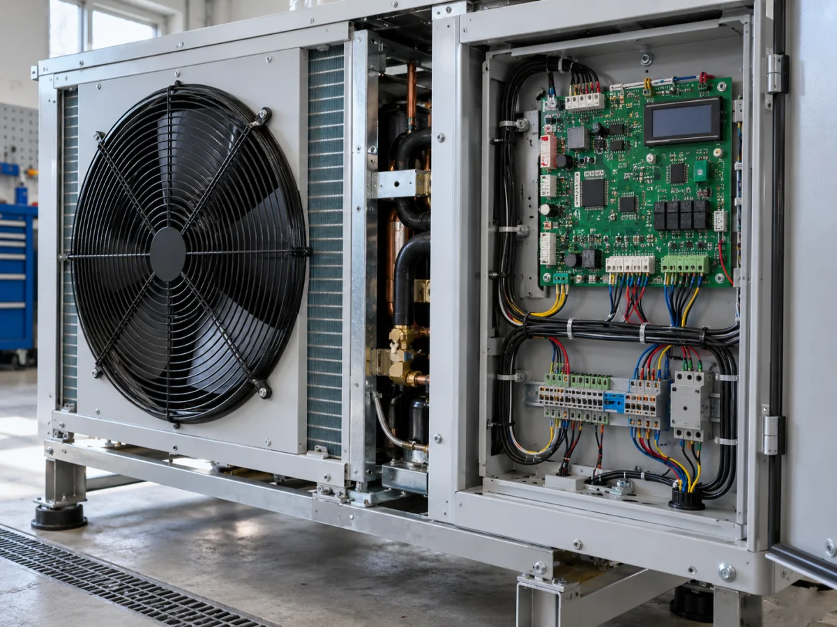
Custom electronic control board with sensor and load connections in an HVAC unit's service compartment
Representative application image.
FocusAn OEM board tailored to the equipment manufacturer
ScopePCB, firmware, display and testing
life cycleModel, revision and service management

Your project, your product

Developed confidentially and delivered with source files.

We may work with a confidentiality agreement (NDA) before sharing technical details. At the end of the project, we deliver the source codes, design files and technical documents we have developed to you.

  • NDA before sharing technical information
  • Clear deliverables agreed at the outset
  • Source and technical files at the end of the project
Our confidentiality and delivery process

VOMRO engineering approach

We translate your device's operating knowledge into its control board and software.

An available controller may suit the first model but become limiting when new sensors, a different display or model-specific sequences are needed. Custom control design jointly defines startup conditions, the measurements used for decisions and responses to faults. Hardware and software are developed from those requirements.

Our focus is the control electronics inside the device. We work at product level with manufacturers of cold-room refrigeration units, chillers, heat pumps and air-handling equipment. Your team's knowledge of mechanical and refrigeration architecture becomes I/O lists, state flows, model options and acceptance tests. Future production and service needs are considered alongside the first prototype from the outset.

01

Custom control PCBs and product architecture for equipment manufacturers

For a new device, the control board, display and power connections can be planned together. An existing-model update requires reviewing retained sensors, wiring harnesses and panel dimensions. Choosing one board or separate control and user-interface boards considers cable lengths, heat, assembly and maintenance. The relationship between high-power sections and sensitive measurements is reflected in the electronics layout.

Custom firmware runs on the board and determines device behaviour. If one board will serve models with different capacities, common functions and changing hardware are separated. Sensor counts, output types and setting limits are documented in a model list. Identification and checking steps can then prevent one model's software or parameters being used on the wrong device.
02

Operating sequences for cold-room units and chillers

In a cold-room unit, temperature measurement, door status, fan operation and defrost are interrelated. Defrost removes ice from the evaporator; its start, termination conditions and subsequent fan restart follow the device architecture. The application is more than on/off control at one temperature threshold. Sensor faults and power interruptions during the cycle are also assessed.

Chiller control may use fluid inlet and outlet temperatures, flow information and pump status. Starting a pump and confirming sufficient flow are separate steps. Startup, standby, capacity demand and shutdown sequences are documented with the manufacturer. Prototypes test these sequences against refrigeration-circuit requirements and equipment documentation.

03

Integration with heat pumps and existing compressor drives

Heat-pump heating, cooling and other operating states require defined sequences and transition conditions. If commanding an existing compressor drive, assess the manufacturer's permitted interface, speed or capacity requests, status feedback and shutdown conditions. Having a communication link does not mean every command is accessible or every drive behaves identically.

Developing supervisory device control and designing the compressor power drive from scratch are separate work packages. When integrating an existing drive, its defined protections and operating limits are respected. Request acceptance, actual running feedback and fault status are monitored separately. Tests cover communication loss and rejected commands.

04

Designing fan, valve and pump outputs for actual loads

Starting a fan, setting its speed and confirming operation may require different interfaces. Relay contacts, analogue commands or manufacturer-supported communication are assessed for the load. Valve travel time, pump inrush current and contactor coils influence output selection. Defining a board only by its total output count is insufficient.

Ventilation and air-handling equipment may use fan status, filter differential pressure, damper position or temperature measurements. Displaying a requested value and confirming actual airflow are separate matters. Document simultaneous loads, shutdown order and the state after power restoration. Test prototypes with the intended motors and drives, not unloaded switching alone.

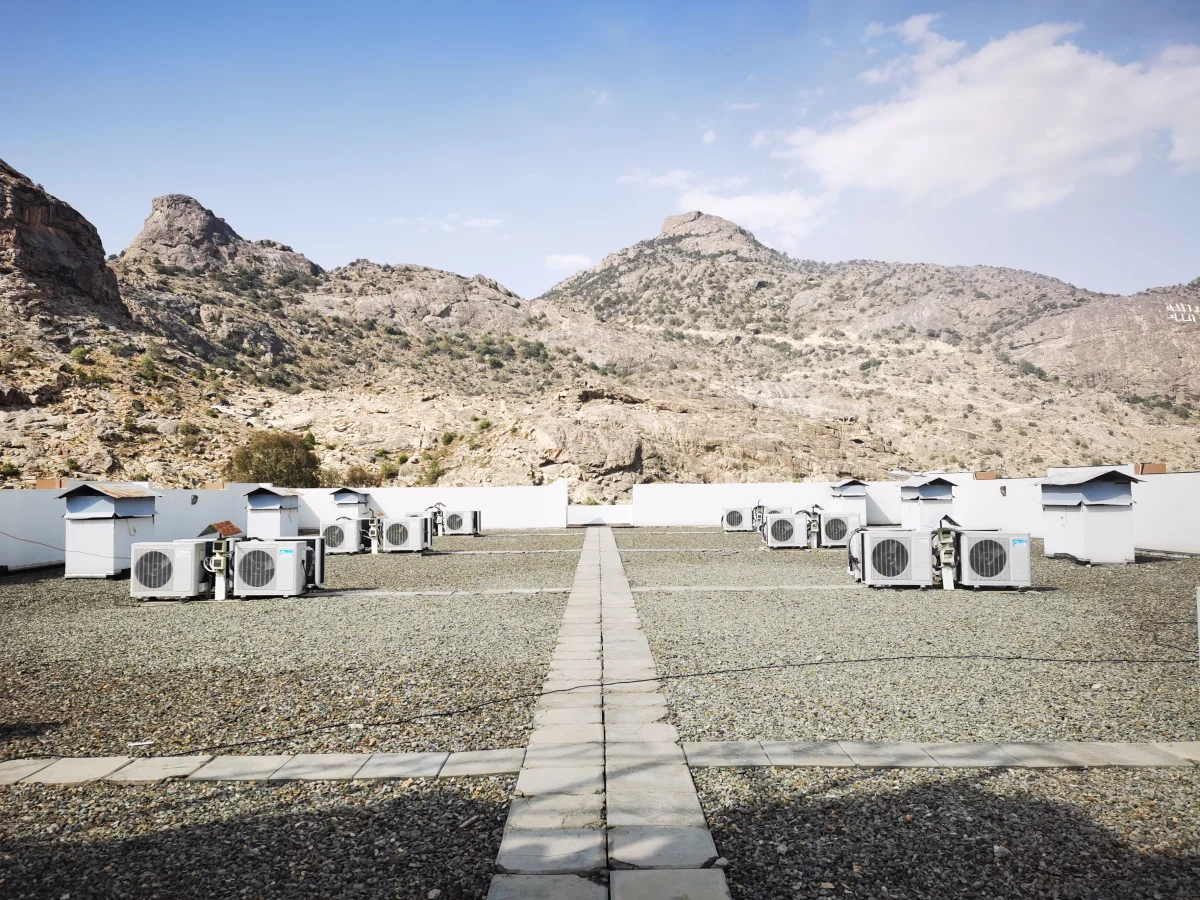
Outdoor air-conditioning units installed on a roof
Outdoor air-conditioning units on a roof.
05

Reliable temperature, pressure and flow measurements

Measurement underpins control decisions. Define temperature probe type, pressure-sensor output and how flow information is obtained. Assess range, cable length, mounting location and electrical influences. A sensor's catalogue accuracy cannot directly represent the accuracy of the complete measurement chain, including board and mechanical placement. The target is assessed on the device using a reference method.

If calibration is required, define production calibration points, the reference instrument and stored coefficients. Disconnected sensors, short circuits and out-of-range values must be distinguished from valid readings. A last valid reading may remain displayed, but it must not enter control decisions as current data. Filtering is evaluated with actual operating data to provide stable readings without missing rapid changes.

06

Fault, power-loss and restart behaviour

Unexpected-condition behaviour is a design requirement alongside normal operation. Define which outputs stop and which tasks may continue after flow loss, sensor failure, drive alarms or power interruption. Different alerts may require different shutdown responses. Appropriate behaviour follows the manufacturer's risk assessment and equipment conditions, with an understandable reason displayed.

Delays limiting rapid compressor restarts and restart conditions follow manufacturer documentation. After power restoration, measurements and required feedback are checked for validity first. Separate faults requiring user acknowledgement from conditions allowing automatic recovery. Required independent protections remain alongside software control; one control board is not assumed to provide all device safety functions automatically.

07

Operator displays, service menus and software versions

Daily operator settings and service technicians' calibration and model parameters are not left unrestricted on the same screen. Clearly display operating state, target and measured values, waiting reasons and fault explanations. Touch or button interfaces follow mounting and use conditions. Permission levels and adjustable limits are defined with the manufacturer.

A service interface can show recent events, sensor readings, operating hours and installed software versions. Connected servicing requires separate planning for permissions and updates; basic device control need not depend on internet access. Consider safeguards against power loss during updates and selection of the wrong model package. Tracking installed versions helps reproduce and investigate field problems.

08

Preparing device variants and production testing together

The first board's power, sensor readings, outputs and display are checked before testing with the target device. Record cycle startup, changing demand, shutdown, faults and restarts. Assess temperature in the closed cabinet, condensation risk, wiring and electromagnetic effects of loads. Required conformity and specialist laboratory work are planned at the outset.

Pilot production establishes repeatable board programming, model configuration, calibration and functional checks. A production fixture can test functions that do not require the complete device; final device testing is defined separately. Hardware, firmware and parameter versions are matched. Document which checks must repeat after supply changes. PCB fabrication and assembly are offered only within customer projects developed by VOMRO.

09

OEM project ownership, confidentiality and technical file delivery

The control system is developed for your device and brand. For a new product, share the operating principle; for an update, identify retained features and problems to solve. At your request, we sign an NDA before technical documents are exchanged. The quotation defines the board, software, display, mechanical interfaces, initial prototype and validation scope. Development costs are assessed separately from subsequent production and testing costs.

Project schematic and PCB sources, firmware, display software, mechanical CAD and technical documents are delivered at completion according to the contractual list. Programming, parameter loading, interfaces and test instructions are defined within that package. Closed software in an existing compressor drive and third-party tools retain their licence conditions. We aim to provide a clear project structure usable for maintenance and later revisions.

Different product requirements in HVAC control electronics
Device requirementCustom development focusInformation needed at the outset
Cold-room refrigeration unitTemperature, fan and defrost sequenceSensors, loads and cycle conditions
ChillerPump, flow and capacity demandRefrigeration arrangement and operating limits
Heat pumpState transitions and drive interfacePermitted commands and manufacturer documentation
Ventilation equipmentFans, valves, dampers and service displayAir path, equipment and model options

How it works

A clear process from start to delivery.

Not every project looks the same; however, the measurable requirement, controlled revision, and field verification steps remain unchanged.

  1. 01

    Let's define the device and models

    Identify operating sequences, sensors, loads and production objectives together.

  2. 02

    Let's develop the board and software

    Prepare the control PCB, firmware and display using shared state and interface definitions.

  3. 03

    Let's validate on the target device

    Assess normal cycles, fault responses and restarting through recorded tests.

  4. 04

    Let's provide the production and service package

    Organise sources, model settings, production testing and technical instructions within the delivery scope.

Frequently asked questions

Before starting the project

The technical scope, deliverables and test plan are clarified together according to the requirements of your project.

Can we develop our own control board as a chiller or heat-pump manufacturer?

A custom PCB, firmware and display scope can follow assessment of the operating principle and equipment. A shared board across models is an option; sensors, loads and model limits are defined together.

Can you work with our existing compressor drive?

We review manufacturer-permitted connections, commands and feedback. If a suitable interface exists, supervisory integration can be assessed. Compatibility with every drive is not promised; validation uses the target hardware and software version.

Does control require internet access or building automation?

Required local control and displays can be planned independently of connectivity. Any interface to external systems is scoped separately for the manufacturer's product. The main work here is developing the device's own electronic control.

How are safety and conformity tests addressed?

Electrical safety, EMC, independent protections and specialist tests follow intended use and target markets. Refrigeration circuits and equipment limits are assessed with relevant specialists. A functioning control board alone is not approval of the completed device's conformity.

Are an NDA, source delivery and subsequent board production possible?

We can work under an NDA before technical information is shared. PCB, firmware, display and mechanical sources developed within scope are delivered according to the contract, with third-party licences explained. PCB fabrication and assembly support are offered only within customer projects we develop.

Let's start with your idea

Let's talk about the product you dream of and the need you want to solve.