
Measure pressure together with its reference

Pressure sensor selection and measurement electronics for your application

A pressure sensor converts pressure applied by a gas or liquid into an electrical measurement. Monitoring a compressor line, detecting filter blockage and controlling a vacuum process require different references and sensors. VOMRO evaluates a suitable sensing element or ready-made transmitter alongside analogue circuitry, embedded software, communication and mechanical connections. The project aims not simply to display a value in bar, but to establish the conditions under which that value is reliable.

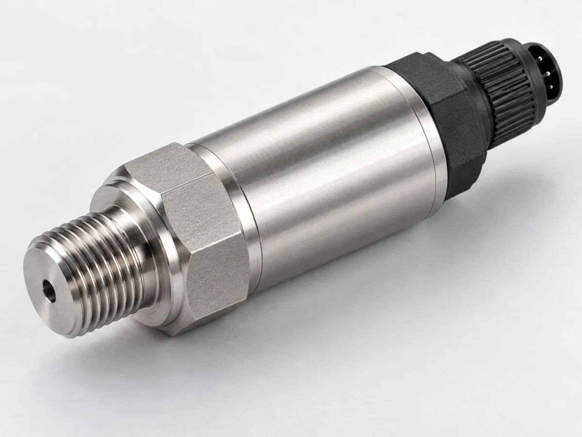
Finished pressure sensor with a threaded process inlet, cylindrical stainless steel body and top connector
Illustrative sensor product image.
ReferenceAbsolute, gauge or differential
InterfaceBridge, voltage, current or digital
SelectionFluid, range and dynamic behaviour

VOMRO engineering approach

Ask 'relative to what?' as well as 'how many bar?'

Requesting a '10 bar sensor' is insufficient. Specify the fluid, normal pressure, transient surges, temperature, connection thread and acceptable error. For example, a low differential-pressure filter monitor may still need to withstand high line pressure. A small measurement difference and a large common-mode pressure are separate requirements.

This is not a product catalogue. It explains decisions involved in developing a new device, a measurement board for an existing machine or a remote monitoring system. If a ready-made transmitter meets the requirement, integrating a suitable component into your device may be preferable to manufacturing a custom sensing element.

The complete measurement process

From sensed quantity to usable data

  1. 01Fluid and reference pressure
  2. 02Diaphragm and sensing element
  3. 03Front end and temperature correction
  4. 04Pressure type, unit and record

Conceptual diagram. The actual measurement range, error budget and validation plan are defined for the application.

01

Differences between absolute, gauge and differential pressure sensors

Absolute pressure references an ideal vacuum, while gauge pressure references local atmospheric pressure. Differential pressure is the difference between two ports. A gauge sensor open to the atmosphere therefore reads approximately zero, while an absolute sensor reads atmospheric pressure. Even with the same unit, values with different references are not directly comparable.

Absolute pressure may suit vacuum packaging, gauge pressure pneumatic line monitoring and differential pressure ventilation filters. Final selection depends on process control. Recording reference type alongside units such as kPa reduces interpretation errors between devices. Where the sensor design has a vent, protection against moisture and blockage is also part of the mechanical project.

02

Measurement range, overpressure and burst pressure are different

The measurement range is where the sensor operates within its specified error limits. Overpressure tolerance describes the limit above that range that can be sustained without permanent damage; burst pressure is a separate limit related to housing integrity. Withstanding overpressure does not mean measuring it accurately. Pulse duration and repetition must also be considered.

For example, a brief pressure spike when a pump stops may not appear on a slow logging display. First measure actual line transients, then determine the required bandwidth and protection. A snubber or restricted passage may provide mechanical protection while suppressing the fast event. The acceptance plan explicitly states the balance between protection and the dynamics to be measured.

03

How are wetted materials and mounting selected?

Even with suitable electronics, measurement cannot be maintained if the diaphragm, seal or fitting material is incompatible with the fluid. Oil, water, refrigerant gas and chemical solutions require different assessments. Check wetted materials, cleaning agents, particles and freezing risk against manufacturer documentation. Stainless steel alone is not a promise of resistance to every chemical.

Define thread standards, sealing surfaces and mounting torque. Sediment blocking a narrow pressure passage or mounting forces on the body can cause field drift. If connections are needed to distance hot fluid from the board, examine response delay too. Reproducing results after removal and reinstallation during servicing matters as much as the first installation.

04

mV bridge output, 0–10 V, 4–20 mA and digital connections

A bare resistive bridge sensor produces a small differential signal. Excitation, a low-drift amplifier, filtering and an ADC are designed together. A suitable ratiometric architecture relates bridge excitation to the converter reference to reduce supply variation effects. In all cases, check input common-mode limits, zero offset and temperature behaviour.

A ready-made 4–20 mA transmitter may suit long field cables, but loop power, load resistance and cable voltage drop must be calculated. Voltage outputs and digital interfaces are also selected for distance and electrical noise. VOMRO projects can define separate software behaviour for broken cables, overrange, communication loss and invalid data alongside the measured value.

05

How are resolution, total error and calibration assessed?

Many display digits are not proof of high accuracy. Zero drift, span error, nonlinearity, hysteresis, temperature effects and long-term drift are separate contributions. Check whether a percentage error in the datasheet refers to full scale or the reading. Continuously using a wide-range sensor near its lower end may be unsuitable, particularly with full-scale error specifications.

Acceptance records include the reference instrument, measurement points, rising and falling pressure steps, settling time and ambient temperature. Adjustment and calibration records are distinguished: correcting a value does not remove uncertainty. For devices exposed to changing ambient temperature, a room-temperature zero adjustment alone is insufficient; required temperature points follow actual use.

06

How is a machine-specific pressure monitoring system planned?

In an example filter-monitoring project, fan status can be recorded alongside the pressure difference between inlet and outlet. A low difference in an inactive system is then interpreted differently from a low difference across a clean filter. A pump tester may record pressure, temperature and time together. These are development scenarios, not completed products or ready-made performance commitments.

The control display keeps units, reference type, last update time and sensor status visible. After a power interruption, the logger must not present an old value as a new measurement. Delays, hysteresis, user permissions and fault notifications are defined alongside alarm thresholds. Accurate board measurement and correct operator decisions are therefore addressed within the same scope.

07

What information is needed for a pressure sensor project?

Initial information may include a process drawing, fluid details, normal and maximum pressures, target error, fastest event and mounting space. The exact model code and datasheet of an existing sensor shorten selection. State whether measurement is for monitoring only or machine control, since the consequences of a fault lead to different design decisions.

Following feasibility assessment, VOMRO defines sensor integration, schematic and PCB, firmware, interface and enclosure development. Prototype quantity, test setup, acceptance limits and source deliveries are clarified in the quotation. If external conformity assessment is needed, testing is planned alongside intended use. A component certificate does not automatically confer the same conformity on the finished device.

Select the pressure reference first; validate the final model against the fluid and operating conditions.
TypeReferenceExample requirementCritical check
AbsoluteIdeal vacuumVacuum processes, barometric monitoringAbsolute range and zero approach
GaugeLocal atmosphereHydraulic and pneumatic linesVenting and mounting environment
DifferentialSecond pressure portFilters, flow and closed tanksCommon line pressure and one-sided loading

How it works

A clear process from start to delivery.

Not every project looks the same; however, the measurable requirement, controlled revision, and field verification steps remain unchanged.

  1. 01

    Define the process

    We gather fluid, pressure reference, surge and temperature limits.

  2. 02

    Select the measurement chain

    We define the sensor, connections, analogue circuit and communication.

  3. 03

    Assemble the prototype

    We test the board, software and mechanical connections together.

  4. 04

    Record acceptance

    We validate results and fault states at pressure and temperature points.

Frequently asked questions

Before starting the project

The technical scope, deliverables and test plan are clarified together according to the requirements of your project.

What is the difference between a pressure sensor and a pressure transmitter?

A sensing element converts pressure into an electrical change. A transmitter generally processes that signal into a defined output such as 4–20 mA or voltage. Manufacturer terminology varies, so output and power characteristics are checked separately.

Do I need a negative-pressure sensor for vacuum?

The quantity to control determines the choice. Vacuum relative to atmosphere can be monitored as a negative gauge value, while actual gas pressure can be monitored with an absolute sensor. The two approaches have different zero references.

Does choosing a higher range protect the sensor?

It can sometimes increase tolerance, but affects resolution and the error budget. Continuous operating range, brief pressure peaks and manufacturer overpressure limits must be examined together.

How long can a 4–20 mA cable be?

There is no universal distance. Calculate the loop using supply voltage, minimum transmitter voltage, load, cable resistance and electromagnetic environment. Communication or isolation requirements also depend on the project.

Is every pressure sensor suitable for water and oil?

No. Wetted surfaces, seals, temperature, cleaning agents and pressure connections must be verified for the fluid. A suitable measurement range alone does not establish material compatibility.

Can you develop a custom reading board for an existing sensor?

After examining the datasheet, output format and target performance, suitable projects can include a reading board, firmware, logging and mechanical integration. The exact scope is defined after feasibility assessment.

Your project, your product

Developed confidentially and delivered with source files.

We may work with a confidentiality agreement (NDA) before sharing technical details. At the end of the project, we deliver the source codes, design files and technical documents we have developed to you.

  • NDA before sharing technical information
  • Clear deliverables agreed at the outset
  • Source and technical files at the end of the project
Our confidentiality and delivery process
Let's start with your idea

Let us define your pressure measurement chain together

Share the fluid, pressure range, target accuracy and connection conditions; we can evaluate custom electronics or ready-made transmitter integration.