
Choose the quantity before measuring the amount of light

Light sensor selection: illuminance measurement, optical windows and integration

A light sensor converts incident optical radiation into an electrical signal, but not every detector measures the same quantity. Monitoring ambient illuminance for display brightness control differs from measuring solar irradiance. Lux expresses illuminance weighted by human visual sensitivity, while W/m² describes radiant power per unit area. VOMRO evaluates the detector, optical arrangement and reading electronics together in the customer's device according to the target quantity.

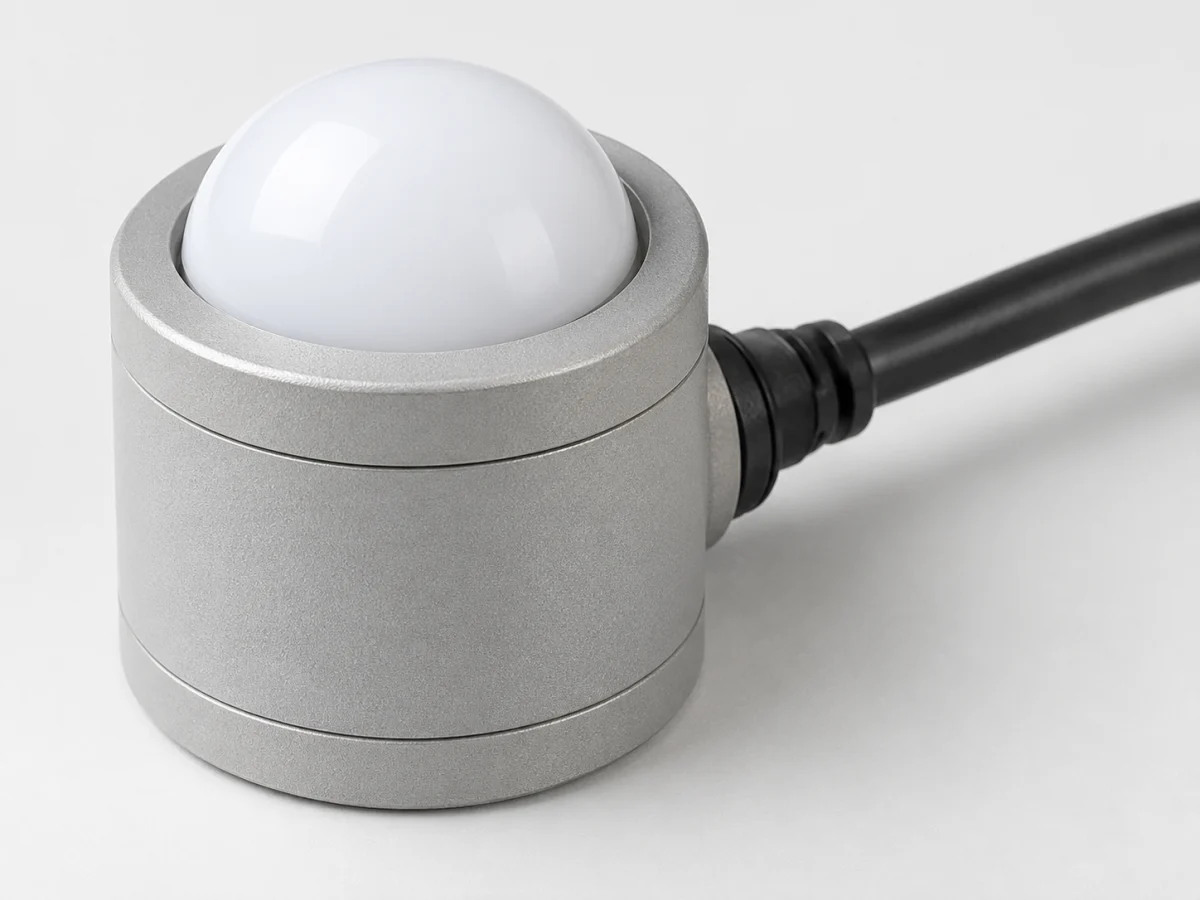
Finished illuminance sensor with an opal light diffuser and enclosed body
Illustrative sensor product image.
IlluminanceLux: weighted by visual sensitivity
Radiant powerW/m²: optical power per unit area
Critical design factorsSpectrum, angle and window

VOMRO engineering approach

Turn 'looks bright' into a measurable requirement.

An automation device may detect daylight to adjust lighting, while another device records changes in a light source on a production line. Human-perceived illuminance matters in the first case; a particular wavelength or source behaviour may matter in the second. The sensor family is selected after this application question has been answered.

The project specifies the measurement plane and field of view as well as the unit. Illuminance falling on a desk and light reaching a sensor on a vertical wall may represent different conditions. Detector orientation, height and optical components in front of it are recorded for a valid comparison.

The complete measurement process

From sensed quantity to usable data

  1. 01Optical field and viewing angle
  2. 02Photodiode and spectral response
  3. 03Optical window and calibration
  4. 04Illuminance or the selected quantity

Conceptual diagram. The actual measurement range, error budget and validation plan are defined for the application.

01

Why are lux and W/m² different?

NIST defines photometry as measurement that accounts for the spectral sensitivity of human vision. Lux is the unit of illuminance in this field. W/m², used in radiometry, describes radiant power per unit area. Even for the same light field, the weighting differs; the two results do not convey the same physical information.

A single lux-to-W/m² conversion factor valid for all sources cannot therefore be used without knowing the source spectrum. For horticultural lighting, UV monitoring or solar radiation, select a method that measures the relevant quantity. Define the acceptance target at the outset rather than presenting an ambient light sensor as another type of instrument merely by adding a calculation.

02

How does simple light detection differ from numerical illuminance measurement?

An LDR, or photoresistor, changes resistance with incident light and can distinguish light from dark using a voltage divider and threshold circuit. Its output is not inherently in lux; numerical illuminance measurement requires a conversion appropriate to the source and detector response. A photodiode produces a light-dependent current; reading that small current requires a suitable analogue front end, gain and, where needed, an ADC.

Integrated ambient light sensors (ALS) combine detection and signal processing. Models designed for lux measurement incorporate filtering and conversion approximating the spectral response of the human eye; digital models may provide data over an interface such as I²C. This can reduce custom analogue reading work, but range, measurement time, saturation and performance behind a window still require examination. Selection considers the quantity, expected sources, interface and enclosure together.

03

How do a tinted cover and small opening affect measurement?

TI's application guide considers window transmittance alongside the sensor's field of view. A dark or small window changes more than appearance; it can affect the light reaching the sensor and its angular response. Validating measurements on a bare development board does not account for the final product cover.

The mechanical design draws the sensor's actual sensitive area, window thickness, separation and viewing aperture together. Prototype measurements with and without the cover are compared under different sources. A correction factor derived from one lamp is tested before being applied to all operating conditions. Optical comparisons are repeated if the material or surface coating changes.

04

How are the source, angle and device's own light tested?

A kiosk display or status LED can illuminate the area of a sensor intended to monitor the external environment. We recommend logging with the display on, off and showing different content during initial design trials. Tuning automatic brightness before checking the device's own influence may amount to compensating for a mechanical problem in software.

The test list includes direct and oblique illumination, different mounting orientations, user shadows and expected source changes. Measurement plane and position are maintained for consistent reference comparisons. If the final installation is accessible, a short field log can reveal usage patterns not seen in bench trials.

05

How are reading electronics and control software developed?

Analogue reading or digital communication is designed according to the sensor output. Records retain the measurement unit, sensor settings and validity. Application behaviour is defined so an exceeded range is not displayed as an ordinary illuminance value. Reading timing is chosen alongside the device's response requirements and power budget.

In automatic lighting, the measured value and driven output can be recorded separately. Pilot trials examine whether suitable delays or hysteresis should be used between on and off decisions. The user's perception of brightness transitions is also part of acceptance. The aim is not merely a stable number, but measurable confirmation of the device's intended operating behaviour.

06

How is comparison with a lux meter planned?

TI's guide shows an arrangement where the reference meter and sensor design observe the same location to assess window effects. In a project, this means using a repeatable fixture rather than holding sensors arbitrarily side by side. The reference instrument's measured quantity and sensing direction must match the candidate device.

The comparison plan defines the level range, source type, direction and stability conditions. Results are stored with the cover's production version and software settings. If a calibration certificate is required, the reference scope and uncertainty are assessed separately. Practical production test steps are developed for dark checks, readings under a known source and fault states.

07

Applications, common errors and project information

Lighting control, display adaptation, internal device light monitoring and custom measurement arrangements are different applications in this field. Common errors include omitting units, ignoring the cover, testing with one source and restricting the sensor's view with a mounting screw. These details should become inspectable features in production drawings.

For VOMRO's review, explain which light is to be measured, in which plane and over what range. Share enclosure images, window material, source types, output interface, target quantity and control behaviour. Detector evaluation, custom electronics, embedded software, optical enclosure and test fixture can be planned together according to the deliverables scope.

  • Distinguish lux targets from radiant power targets.
  • Compare the final covered device using actual sources.
  • Version the measurement direction and window material.
Distinguishing measurement targets in a light sensing project
AimBasic meaningSelection question
IlluminanceLight weighted by visual sensitivity; luxAre we monitoring perceived illuminance?
IrradianceOptical power per unit area; W/m²Which spectral region will be measured?
Light present/absentApplication-specific threshold decisionIs a numerical measurement or a state indication needed?
Source variationMonitoring a selected lighting arrangementAre the source and geometry repeatable?

How it works

A clear process from start to delivery.

Not every project looks the same; however, the measurable requirement, controlled revision, and field verification steps remain unchanged.

  1. 01

    Select the quantity

    We define the unit, range, source and measurement plane.

  2. 02

    Evaluate the optics

    We compare the window, sensor position and viewing aperture.

  3. 03

    We develop the control system

    We integrate reading electronics, logging and user-facing behaviour.

  4. 04

    Test the finished device

    We record comparison results with the actual cover and sources.

Frequently asked questions

Before starting the project

The technical scope, deliverables and test plan are clarified together according to the requirements of your project.

Can lux be converted directly to W/m²?

There is no universal conversion factor. Lux is weighted by visual sensitivity; the relationship depends on the source's spectral distribution.

Does an ambient light sensor measure solar energy?

If the target is solar irradiance, a method suited to that quantity is required. An ambient light sensor's lux output does not provide the same information.

Can I put a sensor behind a dark cover?

It can be considered with suitable optical design. Transmittance, window size and angular effects are measured with the actual cover; correction and placement are adjusted if needed.

Is testing with one lamp sufficient?

If the device will operate under different sources, one source does not represent every condition. Expected sources and mounting angles are compared in the acceptance plan.

Can the display's light affect the sensor?

It can, depending on device layout. Displays and status lights are tested in different operating states to examine their contribution to the ambient measurement.

Can you develop a custom lux measurement board?

After examining the range, sources, window and reference requirements, a scope can be prepared for the sensor reading board, embedded software and comparison fixture.

Your project, your product

Developed confidentially and delivered with source files.

We may work with a confidentiality agreement (NDA) before sharing technical details. At the end of the project, we deliver the source codes, design files and technical documents we have developed to you.

  • NDA before sharing technical information
  • Clear deliverables agreed at the outset
  • Source and technical files at the end of the project
Our confidentiality and delivery process
Let's start with your idea

Let us address light measurement alongside optical and electronic design.

Share the quantity to measure, light sources and device cover; we can prepare sensor selection, custom board and comparison plans.