
Engineering for repeat machine builds

Converting control cabinet systems to custom circuit boards

Do you rebuild the same machine control system with a PLC, relays, timers, sensor interfaces and wiring for every unit produced? VOMRO examines which functions can be combined on a board in repeated projects and develops a custom PCB, embedded software and test infrastructure. Projects producing 10 or more units per year can be a useful starting point for an initial review; the decision is not based on quantity alone.

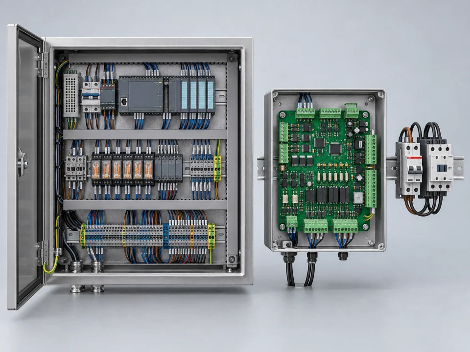
3D illustration showing suitable control functions from a machine cabinet containing a PLC, relays and terminals combined on a custom electronic board
representative application
BeginningRepeated and documented functions
ScopePCB + firmware + integration
DecisionTechnical suitability and total cost

Your project, your product

Developed confidentially and delivered with source files.

We may work with a confidentiality agreement (NDA) before sharing technical details. At the end of the project, we deliver the source codes, design files and technical documents we have developed to you.

  • NDA before sharing technical information
  • Clear deliverables agreed at the outset
  • Source and technical files at the end of the project
Our confidentiality and delivery process

VOMRO engineering approach

If you are re-deploying the same functionality, we can evaluate the production architecture together.

The machine manufacturer may be installing the same PLC program, connecting the same auxiliary relays and wiring the same sensor signals in each order. This repetition creates an opportunity to examine a control board of the product. But it is not necessary to move the entire electrical control panel to a single PCB. The dedicated board only handles sensor processing, sequencing, operator interface or communication tasks, while the off-the-shelf power and safety elements can continue their duties.

We begin by understanding the existing control cabinet schematic, I/O list, PLC program and machine behaviour. We identify model differences, field modifications and service practices among seemingly identical machines. For suitable functions, we prepare custom electronics, firmware, mechanical layout, pilot machine trials and a production inspection plan. The aim is not simply to reduce component count, but to create a customer-specific design with clearly defined production, testing and ongoing maintenance.

01

Which control cabinet projects are candidates for a custom board?

Schemes where repeated machine control, dosing or timing unit, auxiliary sensor interface and many small modules are used together can be examined. The limit of functions, sensor and load types, production plan and recent changes are important. The flexibility provided by an off-the-shelf controller can be valuable if the process is being rewritten on each machine or the existing maintenance team must make frequent changes to PLC.

10 or more units per year is the beginning of a preliminary review to discuss production repetition with VOMRO. It is not an automatic economic threshold or guarantee of savings. The number of models that can use the same board, how stable the design is, and testing/maintenance costs change the result. In some projects, instead of a full control board, a special I/O or communication unit connected to the existing PLC creates a more suitable scope.

02

We transform electrical control panel elements into function and interface maps

Before copying relay labels, we document which event each relay detects, which output it changes and under what conditions. Relationships between timers, counters, analogue converters and operator settings are mapped. The current PLC program is compared with the wiring diagram, and undocumented jumpers or later sensor additions are checked on the actual machine. This exposes differences between the drawing and the operating system at the start of the project.

Signal type, voltage, current, time requirement, cable and connector information are defined in each connection. A configuration table is prepared for the options of the same machine family. Before changing the existing system, it is determined by which test the functions will be compared; Electronic equivalence cannot be promised just by looking at the photo of the electrical control panel.

03

We develop sensor, I/O, relay and driver interfaces together

24 V digital sensors, PNP/NPN inputs, analogue measurements, pulses and encoders use input stages suited to the project. Output circuits for relay coils, valves, indicators and external drivers are selected together with load current, switching frequency and fault conditions. A component's built-in protection does not establish that the completed board is suitable for every load and cable.

If the interface Modbus, CAN or existing PLC/HMI is required, the data map, permissions and timeout are determined. The board's mounting size, terminal orientation, wiring harness and programming connection are evaluated in the mechanical design. Board revision, software version and access to the status of the relevant channel are planned for replacement and diagnostics in the field.

04

We clearly separate power, electrical protection and safety duties

A custom board does not automatically replace required contactors, fuses, circuit breakers, protective earthing or safety circuits. Safety PLCs, safety relays and the drive's relevant safety functions are retained where the architecture requires them. The machine's risk assessment and technical requirements determine which functions belong on the board and which remain in off-the-shelf equipment. Suitable power components and validation scope for mains and high-power circuits are addressed separately.

Isolation between field inputs and the processor, supply protection, and PCB clearance and creepage distances are designed for the operating environment. A plan covers EMC, thermal behaviour and required electrical safety tests. Applicable IEC scope is assessed at product and system level; a reference circuit or certified component does not automatically certify a VOMRO design.

05

We verify control behavior with firmware and pilot machine

PLC program steps are not ported through a literal line-by-line code translation. Startup, ready, running, stopping, fault and service behaviour become firmware requirements. Responses to power loss, sensor disconnection, incorrect parameters and communication loss are defined. Timing-sensitive functions require an explicit target delay and measurement method.

The prototype board is first run on the bench with representative sensors and loads, and then on the pilot machine. The outputs of the old and new architecture are compared based on the same scenarios. The impact of the transition on the production plan and the possibility of returning to the old order when necessary are planned with the customer's team. Findings are recorded with hardware and software revisions; A separate test flow is created for the function control of each produced board.

06

We compare production, service and revision costs as well as part prices.

The comparison includes wiring, program loading, assembly, control and rework as well as available electrical control panel materials. On the custom board side, design, firmware, prototype, fixture, validation, replacement board and maintenance resources are taken into account. It can be seen in the pilot whether the decreasing number of cables or modules actually saves labor. The exact rate is not given without project data.

BOM and critical part alternatives are monitored with the production plan. In field service, board replacement, fault recording and version compatibility with old devices are considered. The manufacturability and maintainability of the design is as important as the cost of the first board. The offer is prepared based on the same functionality, acceptance and delivery scopes.

07

Customer's design, NDA and source file delivery

Before sharing your technical diagram and the specific operation of your machine, we will sign NDA upon your request. We develop the project for the customer's own product and brand. Source code, electronic schematic and PCB resources, mechanical CAD files and technical documents within the scope are delivered at the end of the project. Licenses for third-party tools and libraries are specified separately.

Production deliverables, BOM, connection drawing, compilation/programming steps and test records are defined in the initial deliverable. PCB sample production and electronic component assembly is only offered to customer projects developed by VOMRO. For the initial evaluation, the electrical control panel diagram, current program, sensor/load list and annual production expectation are a sufficient start; We can complete the missing documents together during the review phase.

How it works

A clear process from start to delivery.

Not every project looks the same; however, the measurable requirement, controlled revision, and field verification steps remain unchanged.

  1. 01

    We map out the existing system

    We examine the electrical control panel diagram, current program, I/O and model differences together.

  2. 02

    We separate tasks

    We determine the limits of the custom board, off-the-shelf controller, power and safety equipment.

  3. 03

    We compare with the pilot

    We verify the board and firmware in the same acceptance scenarios as the legacy system.

  4. 04

    We deliver the technical package

    We provide the source, design, connection and test files of the approved revision.

Frequently asked questions

Before starting the project

The technical scope, deliverables and test plan are clarified together according to the requirements of your project.

We produce 10 machines a year. Is a custom board necessarily cheaper?

No. Ten or more repetitions may be the beginning of a preliminary examination. Stability of the function, board development/testing expenses, assembly, service and future production expectation are compared together. Automatic savings based on quantity are not promised.

Will all PLCs, contactors and safety relays be removed?

There is no such requirement. The board can take on suitable control and interface functions while the necessary power, protection and safety components remain in the system. The division of responsibilities is determined through technical review and risk assessment.

Can we share technical files under an NDA and receive the source files?

Yes. Upon your request, we will work with NDA before technical sharing. The developed source code, PCB/CAD resources and technical documents are delivered to the customer at the end of the project; Third party licenses are disclosed separately.

Let's start with your idea

Let's talk about the product you dream of and the need you want to solve.