We solve movement and structure together

Machine design and mechanical system development

We develop mechanical designs for custom machines, devices and products. Travel distance, load, cycle time and installation space determine the mechanism, which is planned to work with the motor, sensors and electronic control. Machine design scope is defined through part and assembly models, technical drawings and functions to be verified on the prototype.

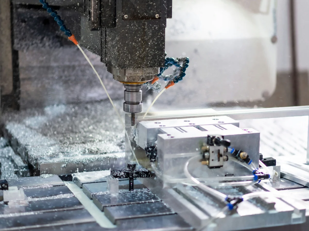
Machining aluminum parts with coolant on the CNC machine
Example of metalworking with CNC on prototype parts.
ScopeMechanism + construction
IntegrationElectronics and control
Output3D model and technical files

Your project, your product

Developed confidentially and delivered with source files.

We may work with a confidentiality agreement (NDA) before sharing technical details. At the end of the project, we deliver the source codes, design files and technical documents we have developed to you.

  • NDA before sharing technical information
  • Clear deliverables agreed at the outset
  • Source and technical files at the end of the project
Our confidentiality and delivery process

VOMRO engineering approach

The beginning of mechanical design is understanding the work to be done.

Preparing a three-dimensional drawing of a part and designing a working machine are not the same scope. It should be explained what work the mechanical system will do, how much load it will carry, what movement it will perform, how often, and how it will interact with the operator. VOMRO bases the design on these requirements and verification objectives.

In new product development projects, later adaptation of the mechanical part to electronics may cause problems. The location of the motor, sensor, cable, control board and connection elements are determined together with the architecture. Thus, monitoring movement, enabling assembly, and accessing parts during maintenance can be addressed in the same design evaluation.

01

Operating cycle and mechanism selection in custom machine design

Functions such as linear or rotary movement, positioning, conveying, clamping or product placement are divided into separate subsystems. Travel distance, speed, repeatability expectation and cycle conditions are defined. The appropriate transmission element and drive approach is evaluated within these limits; A balance is established between ready-made components and special parts.

At the concept stage, the space, number of parts, maintenance and cost effects of different mechanisms are compared. If the uncertainty of a critical move is high, a prototype of that part can be prepared first. This approach allows the operating principle to be tested in real conditions before the entire machine is detailed.

  • Operating cycle, load and motion requirements
  • Evaluation of mechanism and drive options
  • Identification of control and sensor connections
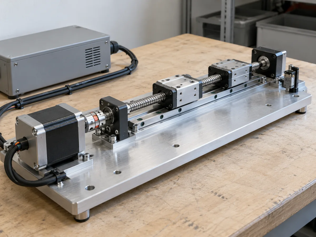
Mechanical motion prototype consisting of linear slide, motor and sensors
Representative application image.
02

Parts, connections and manufacturing details

Parts, connections and movement limits are examined on the three-dimensional assembly model. When selecting materials and manufacturing methods, loads, working environment, target quantity and supply are taken into consideration. Options such as sheet metal, machined part, standard profile or 3D prototype can serve the same purpose with different costs and tolerances.

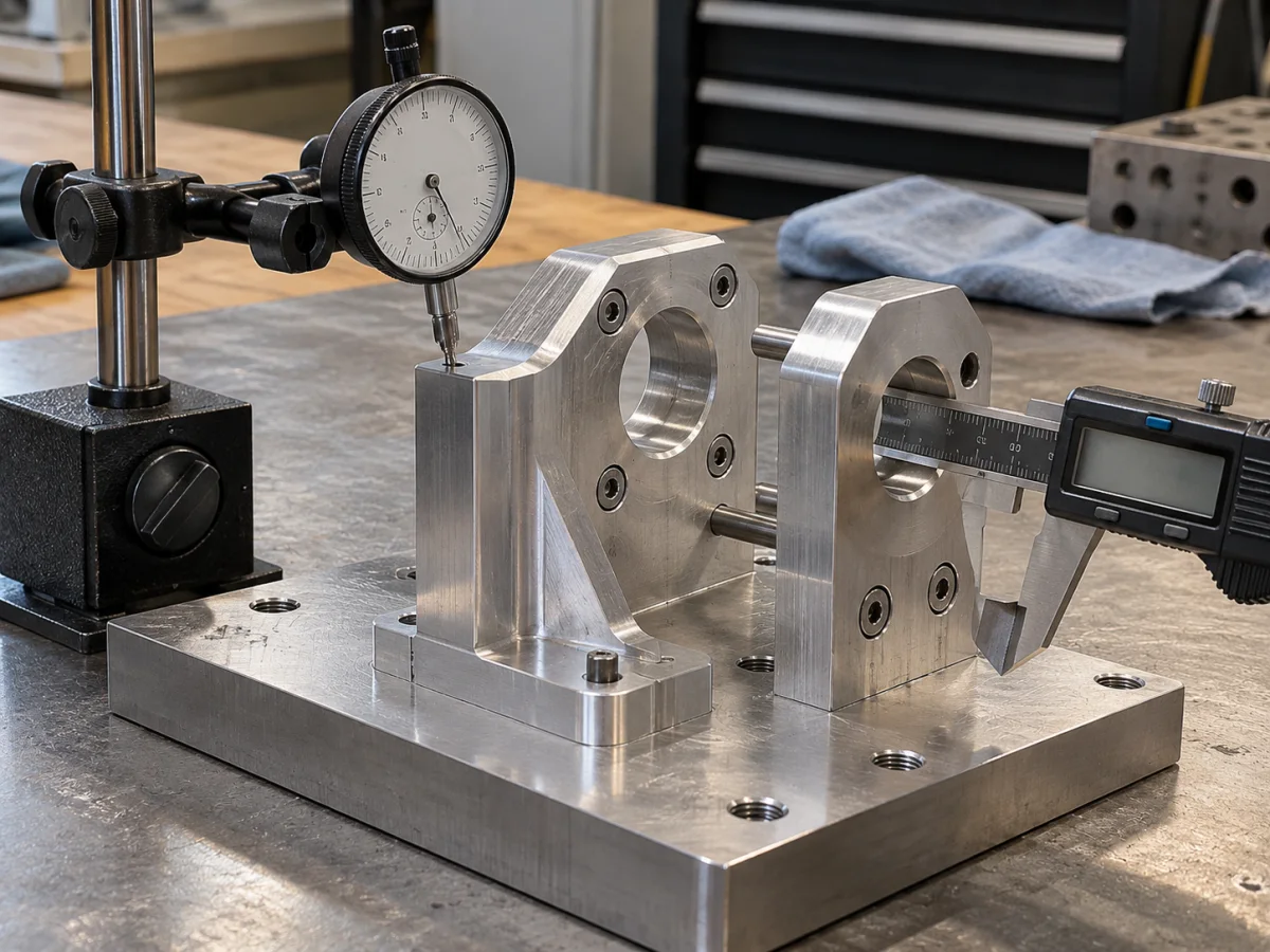
Tolerances and reference surfaces determine assembly repeatability as well as drawing detail. We assess the required fits at shafts, bearings, guides and connections. The model accounts for cable routes, access space and assembly sequence. Engineering calculations and additional analysis are scoped separately as needed.

  • 3D part and assembly modeling
  • Material, tolerance and production method decisions
  • Technical drawings and parts list preparation
Checking the assembly fit of machined parts with callipers and a dial indicator
Representative application image.
03

Verifying mechanical movement with control system

Prototype evaluation covers actual loads and operating conditions as well as no-load operation. Tests may include jamming, backlash, vibration, heating and the effects of repeated movement on connections. Sensor positions and motor control are adjusted alongside mechanical behaviour, and software commands are compared with the resulting motion.

Deliverables may include the assembly model, part models, technical drawings, bill of materials and specified test findings. Risk assessment, guards and conformity work required for manufacture and use are planned separately for the application. A working mechanical prototype does not establish that all operational and safety verification is complete.

  • Assembly and actual load function check
  • Sensor, motor and control system integration
  • Preparing revision and production documentation
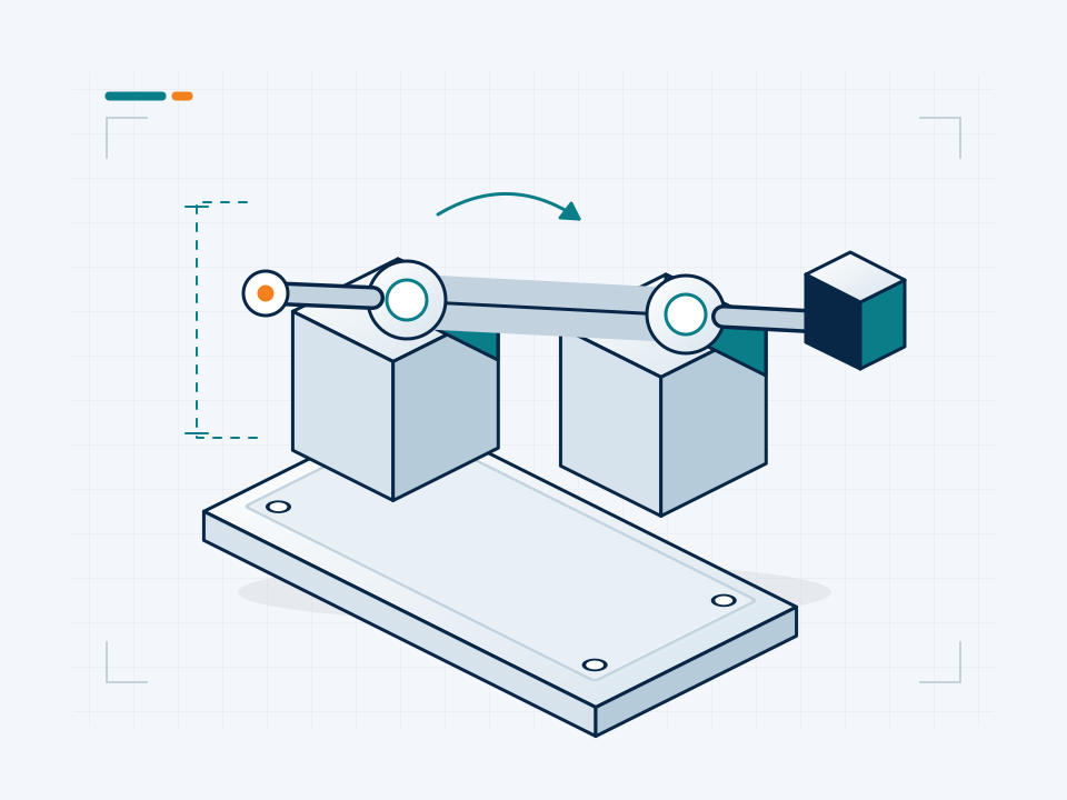
Mechanical structure, motion mechanism, sensors and control components of a custom machine
Conceptual representation of the technical process.

How it works

A clear process from start to delivery.

Not every project looks the same; however, the measurable requirement, controlled revision, and field verification steps remain unchanged.

  1. 01

    We define the job

    We translate load, motion, cycle and usage environment into measurable requirements.

  2. 02

    We set up the mechanism

    We evaluate alternative structures and drive options within technical limits.

  3. 03

    Develop the details

    We model parts, connections and assembly in accordance with the production method.

  4. 04

    We verify

    We test the motion, load behavior and control integration of the prototype.

Frequently asked questions

Before starting the project

The technical scope, deliverables and test plan are clarified together according to the requirements of your project.

Can machine design include electronic control?

Yes. Depending on the project, custom electronic circuit boards, sensors, motor driving and embedded software can be developed together with the mechanical system. Interfaces and scope of delivery are defined from the beginning.

Can you improve an existing mechanism?

The problem can be examined with an existing model, drawing or working example. The scope of revision is determined by evaluating the desired capacity change, right of use and design limits.

Are manufacturing files delivered after design?

Yes. We deliver the 3D models, technical drawings, parts lists and production documents we developed within the scope of the project at the end of the project. File formats and delivery list are clarified at the beginning.

Can we work with NDA before sharing technical details?

Yes. We can complete the NDA arrangements together before you share your project's technical details.

Let's start with your idea

Let's talk about the product you dream of and the need you want to solve.