
Sensors, cables and interfaces must work together in marine conditions

Custom measurement systems for ship and marine sensors

Ship and marine sensors cover different sensing elements for monitoring tank levels, bilges, pressure, temperature and machinery condition. Seawater contact, condensation, vibration, salt exposure and long cables require decisions beyond those of a land-based prototype. For suitable projects, VOMRO develops sensor integration, custom boards, embedded software and mechanical enclosures together. The connected ship system, installation location and required conformity assessments are defined during feasibility work.

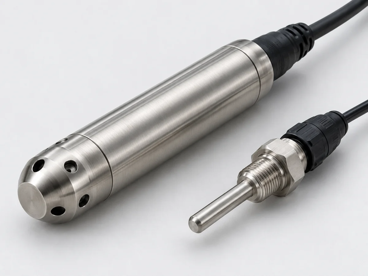
Marine temperature sensor with a sealed connector alongside a waterproof cabled level and pressure probe
Illustrative sensor product image.
MeasurementLevel, pressure, temperature and status
EnvironmentHumidity, salt, vibration and motion
IntegrationActual vessel network and installation conditions

VOMRO engineering approach

Measurement points on a vessel do not all face the same environmental conditions.

A dry control cabinet, open deck, bilge and machinery-mounted sensor encounter different temperatures, water exposure and vibration. One housing, connector or communication option cannot cover every marine project. Describing each measurement point's purpose, mounting and maintenance access is the first step.

This guide is for those connecting existing sensors to monitoring systems, developing data acquisition modules or commissioning custom devices. Its scenarios do not claim ready-made products or completed vessel installations. VOMRO's development work and deliverables are clarified through technical assessment of the application.

The complete measurement process

From sensed quantity to usable data

  1. 01Measurement point and marine environment
  2. 02Suitable sensor and materials
  3. 03Isolation and protocol interface
  4. 04Valid data, alarms and records

Conceptual diagram. The actual measurement range, error budget and validation plan are defined for the application.

01

Which quantities do ship sensors monitor?

Continuous level in service-water and fuel tanks, point liquid detection in bilges, pump pressure and machinery temperature are different measurement tasks. A continuous level value and an overflow or low-level switch do not represent the same function. VEGA's marine applications show these separate requirements for tanks, bilges and engine rooms.

A monitoring module may, for example, need to log tank level and read a bilge switch. Analogue unit conversion and broken-wire behaviour for the switch are then designed differently. Each input defines its quantity, normal range, alarm meaning and state displayed after data loss. Channel count alone does not reliably describe the function.

02

How are tank level, tilt and sloshing assessed?

In hydrostatic level measurement, pressure relates to liquid density and height above the measurement point. Gas-space pressure must also be considered in a closed tank. Radar, capacitive and other methods have different geometry and environmental effects. Tank drawings, liquid type, foam, sediment and maintenance access determine the suitable method.

Vessel motion can change local levels. If tank quantity is required, converting height at one point into litres may be insufficient; geometry and attitude are evaluated. Digital filtering that smooths sloshing also affects alarm delay. Kistler's dynamic pressure applications show that moving liquids can impose rapid loads on tank structures. Steady level monitoring and slosh-impact measurement therefore require different sensor and sampling objectives.

03

Corrosion, material compatibility and sealing

In marine environments, assess diaphragms, fittings, seals and cable jackets alongside housings. Continuous seawater contact differs from exposure to salty air. Select materials for the actual liquid, temperature, cleaning method and expected life. Describing a surface as stainless does not establish suitability for every marine application.

Connections combining different metals require separate assessment of galvanic corrosion through mechanical and electrical design. Enclosure protection must be evaluated for the completed assembly, including cable entries and connectors. Condensation, opening during servicing and incorrectly tightened glands can cause field problems. VOMRO projects can include the bill of materials, assembly layout, sealing target and necessary environmental trials in acceptance scope.

04

Analogue inputs, ground potential differences and galvanic isolation

Transmitter current or voltage outputs, resistive level senders and dry contacts need different input circuits. Taking a parallel measurement while retaining an existing gauge can alter sender loading and gauge accuracy. General compatibility is not assumed without examining the exact sensor model, original gauge and power connections.

Long cables require assessment of ground potential differences and noise between devices. Appropriate galvanic isolation can separate unwanted current paths, but does not solve every corrosion or interference problem. Actisense emphasises preserving isolation according to device connections in marine interfaces. Protective earth, shields, power return and data reference are shown clearly in drawings; different functions are not joined arbitrarily.

05

NMEA 2000, NMEA 0183 and other vessel interfaces

NMEA 2000 is a CAN-based marine electronics network; sending an ordinary CAN message does not establish NMEA 2000 compatibility. Data messages, device identity, network behaviour and connections follow the relevant standard. NMEA defines licensing and certification for products reading or transmitting this information. Network compatibility is assessed separately within the project's development and certification scope.

NMEA 0183 uses a different interface approach. Check serial electrical levels, transmitter/receiver arrangements, baud rate and supported sentences. A gateway between networks is not assumed to convert every message automatically. For Modbus or another machinery interface, examine the actual device's register map and electrical connections separately. Matching connector appearance or protocol names does not prove matching data meanings.

06

Data quality, alarm behaviour and field validation

A vessel monitoring display needs units, source identity and last update time alongside the number. After communication loss, the previous value must not appear to be a new measurement. Example software scope may include channel states, broken-wire notification, overrange, event logging and controlled startup after power returns. Alarm delay and hysteresis follow the application.

Acceptance testing uses actual sensors and cables with the intended display. Supply changes, restarting and line interruptions may be tested. Vibration, humidity, temperature and electromagnetic assessments required by the installation are planned separately. Vessel class, flag and application approvals are determined with responsible parties; a general environmental test is not presented as approval for all marine conditions.

07

Initial technical information for a marine sensor project

Initial information can include vessel type, measurement purpose, mounting location, liquids and temperature and pressure ranges. Sensor and display model codes, network drawings, cable distances and power details reduce integration uncertainty. For tanks, geometry, volume tables and accepted motion conditions during measurement are particularly useful.

VOMRO can quote a practical scope for sensor integration, analogue boards, firmware, logging interfaces and custom enclosures. Differences between the prototype and vessel-installed version, test locations, installation responsibilities and third-party assessments are documented at the outset. Documentation may include cable plans, connection lists, version information and acceptance records. How to enter calibration for a replacement sensor is also considered, keeping the measurement chain clear after maintenance.

Marine design priorities vary by measurement location.
ApplicationMeasurement needKey check
Service-water or fuel tankLevel / quantityGeometry, density, tilt and materials
BilgeLiquid presence / high levelContamination, access and line diagnostics
Pump and hydraulic linePressure / temperatureSurges, vibration and connections
Open-deck moduleEnvironmental or equipment dataSalt, water ingress and connectors
Research and dynamic testingRapid pressure changes or motionBandwidth and simultaneous logging

How it works

A clear process from start to delivery.

Not every project looks the same; however, the measurable requirement, controlled revision, and field verification steps remain unchanged.

  1. 01

    Examine the installation

    We define measurement points, environment, sensors and the existing vessel network.

  2. 02

    Define the architecture

    We match inputs, isolation, power and the data interface.

  3. 03

    Assemble the prototype

    We test electronics, software and the enclosure with actual components.

  4. 04

    Document acceptance

    We record field connections, fault states and defined environmental tests.

Frequently asked questions

Before starting the project

The technical scope, deliverables and test plan are clarified together according to the requirements of your project.

Can an industrial sensor be used directly on a vessel?

Even with a suitable range, materials, enclosure, vibration, power and required approvals must be assessed separately. No general suitability promise is made without knowing location and function.

Is every CAN-output sensor NMEA 2000 compatible?

No. NMEA 2000 defines additional messages and network requirements over CAN. Licensing, product identity and certification conditions must also be assessed.

Are NMEA 0183 and NMEA 2000 the same network?

No. They use different electrical and data structures. Supported sentences and messages are mapped in a gateway; every item is not assumed to convert in both directions.

Does filtering remove quantity errors in a sloshing tank?

Filtering can steady the display, but does not alone remove uncertainty from tank geometry and motion. Delay and alarm behaviour are measured too, and a suitable application method is selected.

Does galvanic isolation completely prevent corrosion?

No. Where appropriate, it can separate unwanted electrical connections, but material combinations, water contact, mounting and other corrosion causes require separate assessment. Protective connections and data isolation serve different purposes.

Can you transfer existing vessel sensors to a new display?

After reviewing sensor and display models, interfaces and network drawings, suitable projects can include data acquisition and integration. Existing gauge loading, message support and acceptance tests are defined in the scope.

Your project, your product

Developed confidentially and delivered with source files.

We may work with a confidentiality agreement (NDA) before sharing technical details. At the end of the project, we deliver the source codes, design files and technical documents we have developed to you.

  • NDA before sharing technical information
  • Clear deliverables agreed at the outset
  • Source and technical files at the end of the project
Our confidentiality and delivery process
Let's start with your idea

Let us examine your vessel's measurement and connection conditions together

Share sensor models, mounting locations, the vessel network and target display; we can make the data acquisition, custom board and mechanical integration scope concrete.