
Fuel measurement requires physics, electronics and the platform to be considered together

Aircraft fuel sensors and fuel measurement electronics development

Aircraft fuel sensors perform different tasks, including monitoring tank level or quantity, line flow, temperature and other properties. These tasks are not interchangeable. Deriving reliable fuel quantity from a capacitive probe requires tank geometry, fuel properties, aircraft attitude and fault behaviour to be considered together. For suitable projects, VOMRO defines research, ground-test setup, prototype and custom measurement electronics work through technical feasibility assessment. In-flight use and approval scope must be defined separately.

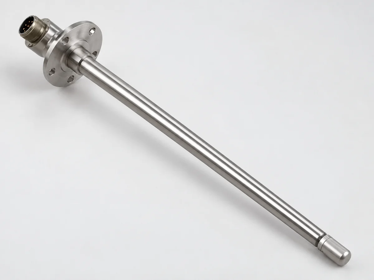
Finished capacitive fuel quantity probe with a long metal sensing body, upper mounting flange and sealed connector
Illustrative sensor product image.
MeasurementLevel, quantity, flow or property
ArchitectureProbe, tank model and electronics
ScopeFeasibility, prototyping and validation

VOMRO engineering approach

First define which fuel information the sensor must provide.

A ground-test instrument and an in-flight fuel quantity indicating system have different requirements. A connection or fault response acceptable on a test rig may be unsuitable on an aircraft. Platform type, development responsibilities and how the output will be used are initial project inputs.

This page is a technical guide to measurement methods and project decisions. It does not claim that VOMRO offers ready-made approved aircraft parts, holds airworthiness authority or has compatibility with a particular aircraft. Platform approval responsibilities and current requirements are identified at the start of development planning.

The complete measurement process

From sensed quantity to usable data

  1. 01Tank geometry and fuel
  2. 02Level, quantity or flow channel
  3. 03Geometry and environmental assessment
  4. 04Validated development output

Conceptual diagram. The actual measurement range, error budget and validation plan are defined for the application.

01

Why distinguish fuel level, quantity, flow and quality?

Level describes fuel height in a particular tank region. Volume relates to tank geometry, while mass also depends on density. Flow is fuel passing through a line per unit time. Consumption calculated from line flow is not an independent tank quantity measurement unless the initial amount and all relevant flows are correctly known.

Fuel quality is not one quantity. Water, contamination or another property requires a method suited to that target. Changes in a level probe signal may provide diagnostic information under some conditions, but do not automatically prove fuel usability or compliance with a standard. The interface separately names litres, kilograms, flow and faults; records preserve the origins of measured and calculated results.

02

How does a capacitive aircraft fuel sensor work?

In a capacitive probe, the dielectric properties of the medium between electrodes affect the measurement. Capacitance changes as the fuel-covered portion of the probe changes. FAA training material explains this principle; actual systems may contain several probes and additional sensing elements. Capacitance is not directly the litres or kilograms in the complete tank.

Electronics read the probe through defined excitation and measurement methods. Cable capacitance, leakage, contamination and connections are also part of the measurement. Laboratory work can first test the reading chain using equivalent electrical loads, then examine the actual probe in a suitable setup. Electrical energy limits inside the tank are not selected solely for sensitivity; protection and fault-analysis requirements must be design inputs.

03

Tank geometry, probe position and fuel density

Level and volume may be easily related in a uniform laboratory vessel, but not in an irregular wing tank. Probe placement and the tank model are evaluated together. Crane explains that fuel quantity systems may pass probe information through an electronics unit or data concentrator to calculate total fuel. Architecture varies by platform.

Density matters in mass calculation. Fuel type and temperature-dependent properties can limit fixed-coefficient approaches. Collins Aerospace provides an example of this need through direct-density measurement solutions; this is not a VOMRO performance claim. The project defines fuel, mixture limits, temperature and expected density behaviour. Tank models, calculation coefficients and test data can share version control.

04

How are attitude, sloshing and data validity handled?

When the tank tilts or fuel moves, the same total quantity can produce different levels in different regions. Testing is therefore not limited to a level, stationary tank. Required accuracy at different attitudes follows platform use. Filtering can steady the display, but is not assumed to eliminate physical uncertainty.

An example development study may log raw channel data, calculated quantity, attitude inputs and validity together. Filter delay, startup and missing-channel behaviour are measured. Old values remaining on screen are distinguished from new valid measurements. Independence of additional functions such as low-level warnings is not accepted merely because a second software threshold exists; it must be justified by architecture and fault assessment.

05

Project scope for measurement electronics and embedded software

Custom electronics development defines probe excitation, capacitance reading, temperature channels, power protection and communication as a whole. Interfaces follow the actual connected system's electrical and data definitions. Listing a protocol name does not establish compatibility with a particular aircraft connection. Message scales, update times and fault states are examined separately.

Firmware requirements may include unit conversions, coefficient versions, range checks, channel diagnostics and record formats. Software developed for a test rig is not assumed to have the same approval scope as flight software. VOMRO quotations define schematic/PCB, software and mechanical sources, integration responsibilities and validation tools as separate deliverables. Documentation access and usage terms for third-party probes and software are also evaluated.

06

Fuel tank safety and limitations on aircraft use

FAA AC 25.981-1D provides guidance on demonstrating compliance for preventing non-lightning ignition sources in transport-category aircraft tanks. Its scope does not apply uniformly to every aircraft. The platform's certification basis, electrical fault conditions and environmental requirements must be established with the responsible parties. Low board power consumption in normal operation alone is not proof of tank suitability.

Protection is assessed alongside potential faults, wiring, connectors and effects from the system. A working prototype, a passed environmental test or a component certificate does not constitute aircraft installation approval. Responsibilities for ground trials, development prototypes and final installations requiring approval are clearly distinguished. The contract specifies VOMRO's technical data deliverables and external assessments.

07

What information is needed for calibration and project startup?

The electronic reading chain is validated with known electrical references, while quantity calculations use defined tank and filling conditions. Records retain the tank geometry model, filling steps, reference quantity method, temperature and attitude. Acceptance targets specify whether error is a percentage of full scale, actual quantity or a combination.

Start with the platform type, research or intended use, tank drawing, fuel definition, operating temperature, quantity range and target interface. For an existing probe, share the model code and technical documents you are permitted to provide. The first phase may be method feasibility, an electrical simulator, a tank trial or a comprehensive electronics prototype. Success conditions and decisions on progressing are made concrete without creating an expectation of a ready-made flight product.

Fuel measurement tasks differ; define the method and platform validation separately for each task.
TaskInformation providedAdditional assessment required
LevelSignal related to local fuel heightProbe position and tank attitude
QuantityVolume or massTank geometry; density for mass
FlowFuel flow over timeFlow directions, range and consumption calculation
TemperatureLocal fuel temperaturePlacement and response time
Quality-related measurementA defined property or contaminantProperty-specific method and reference analysis

How it works

A clear process from start to delivery.

Not every project looks the same; however, the measurable requirement, controlled revision, and field verification steps remain unchanged.

  1. 01

    Define the intended-use scope

    We define the platform, ground-test or flight objective and responsible parties.

  2. 02

    Examine the measurement method

    We match tank, fuel, probe and electronics architecture during feasibility assessment.

  3. 03

    We develop the prototype

    We integrate reading electronics and software in the defined test setup.

  4. 04

    Document the results

    We record acceptance data, limitations and the next validation step.

Frequently asked questions

Before starting the project

The technical scope, deliverables and test plan are clarified together according to the requirements of your project.

Does VOMRO sell ready-made, flight-approved fuel sensors?

This page does not claim a ready-made or flight-approved product. Custom electronics and integration development are defined through feasibility assessment; aircraft-use responsibilities and the approval route are established separately.

Does a capacitive probe directly measure kilograms?

The probe produces a capacitance-related signal. Quantity calculation requires a tank model and, depending on architecture, additional information; mass calculation relates to density. Conversion and validation take place at system level.

Does remaining fuel calculated from flow replace tank measurement?

Consumption calculations depend on the initial quantity, all relevant flows and measurement errors. They are not the same information source as independent tank quantity measurement; the architecture follows platform requirements.

Will the same sensor work in every tank?

Electrical reading may be possible without guaranteed quantity accuracy. Tank geometry, probe location, fuel properties and attitude conditions are reassessed, with acceptance conditions defined for each application.

Does a level sensor verify fuel quality?

Generally, no. A particular contaminant or property requires a suitable validated method. A level-signal change alone must not be interpreted as proof of compliance with a fuel standard.

Can development start with a ground-test setup only?

A suitable scope can start with an electrical simulator, probe-reading prototype or data acquisition setup. The test environment, acceptance criteria and subsequent product stage are planned separately.

Your project, your product

Developed confidentially and delivered with source files.

We may work with a confidentiality agreement (NDA) before sharing technical details. At the end of the project, we deliver the source codes, design files and technical documents we have developed to you.

  • NDA before sharing technical information
  • Clear deliverables agreed at the outset
  • Source and technical files at the end of the project
Our confidentiality and delivery process
Let's start with your idea

Define your fuel measurement project using technical data

Share the platform, tank structure, fuel and development objective; we can establish a concrete scope for feasibility work, ground testing or a custom electronics prototype.