
Custom development for machine manufacturers

Agricultural machinery electronics, control boards and embedded software

Combine harvesters, forage harvesters, seed drills, sprayers, balers and crop sorting lines each have different electronics requirements. VOMRO develops electronic control boards, embedded software, sensor interfaces, operator displays and remote monitoring systems for agricultural machinery manufacturers and companies developing their own equipment. We plan a project suited to your self-propelled, trailed, mounted or stationary machine by considering electronics, software and mechanical design together.

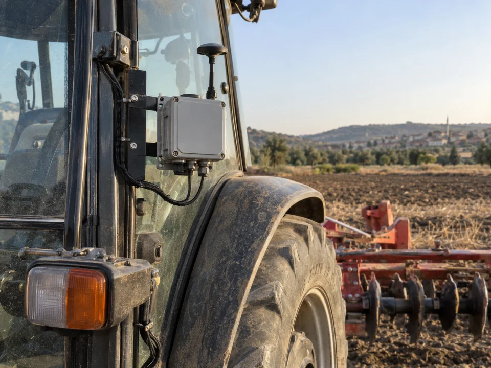
Representative application of an enclosed data collection device and antenna fixed to the tractor cab
Representative application image.
HardwareSensor + control + interface
SoftwareLocal functionality + recording + telemetry
How it worksCustomer specific project

Your project, your product

Developed confidentially and delivered with source files.

We may work with a confidentiality agreement (NDA) before sharing technical details. At the end of the project, we deliver the source codes, design files and technical documents we have developed to you.

  • NDA before sharing technical information
  • Clear deliverables agreed at the outset
  • Source and technical files at the end of the project
Our confidentiality and delivery process

VOMRO engineering approach

We derive the control board requirements from the agricultural machine's operating cycle.

Monitoring seed flow during sowing, indicating a stopped mechanism in a combine harvester, recording fertiliser quantity and sending dryer measurements to a server are different needs. We examine machine operation with you and define sensors, motors and valves, operator settings and required reports. Our agricultural machinery electronics service is not limited to a particular vehicle: tractor-mounted equipment, a self-propelled harvester or a fixed facility unit can all be project subjects.

The scope of work can be a new electronic control unit (ECU), a measurement module added to an existing machine, a control panel or a device that transmits machine data to the server. The first sample, trial on the machine, production cost and delivery of technical files are handled in the same plan. The following applications describe the project scopes we can develop; The solution that suits your needs is determined after your machine is examined. You can share the technical details of your project with the confidentiality agreement (NDA).

01

Sowing and planting machines: seeder, precision sowing and seedling planting electronics

Electronics can be developed to monitor seed or seedling flow, metering mechanism speed and hopper level in mechanical or pneumatic seed drills, precision planters and transplanting equipment. Interrupted flow in individual rows, a mechanism that stops rotating or an empty hopper are clearly indicated to the operator. The machine's mechanism is used to validate which control board signal represents an actual sowing event; the target sowing rate is kept distinct from the value measured by the sensor.

Requirements such as electric metering motors, row shutoff and variable-rate sowing are assessed together with speed data, motor response and connection to the existing terminal. User interface workflows are prepared for settings, calibration and operating records. Testing on the machine with different seed sizes, dust, vibration and operating speeds goes beyond a sensor that counts correctly on the bench. A common board with different connection options can also be designed for the manufacturer's range of machine models.
02

Tillage, hoeing and inter-row cultivation machines

Electronics for ploughs, cultivators, disc harrows, rotary tillers, rollers and hoeing machines may monitor working position, mechanism speed, movement counts or specified sensors. We define measurement points, adjustment methods and the information operators need. This clarifies the different scopes of an operating-hours counter and a controller that adjusts using position feedback.

Camera- or sensor-based row detection can be considered for inter-row hoeing and mechanical weeding. Displaying the detected position and automatically commanding a moving mechanism are separate development stages. Field trials cover plant structure, lighting, dust and travel speed. Functions are defined while preserving mechanical guards and the machine's safety architecture.

03

Control boards for sprayers, mist blowers and fertiliser application machines

Control electronics using pressure, flow, tank level and section valves can be developed for field sprayers, orchard sprayers and other spraying equipment. The operator's target application rate and measured flow are shown separately. Dose control as speed changes, section switching sequences and sensor-fault warnings are defined with the machine manufacturer. The customer's expertise determines agricultural application values; electronics support their implementation and recording.

Weighing, cover position, distributor speed or flow information can be used in solid fertilizer spreading, organic fertilizer distribution and liquid fertilizer application machines. Position data, mechanical response and terminal support for variable rate fertilization and automatic section control are also examined. The result of the distribution on the field is verified with the machine settings and material. The goal is to enable the manufacturer to manage the settings and operating information of his own machine by designing a board and software suitable for the model.

04

Measurement, displays and data collection in combine and forage harvesters

Auxiliary devices for combine harvesters, reaper-binders, forage harvesters and cotton harvesters may collect mechanism speeds, crop flow, hopper level, temperature and operating time. Sensor selection and alarm conditions are defined together to detect a stopped section or signs of blockage. Where harvest data is linked to location, timestamps, sensor identity and calibration information are also stored. A sensor signal is not treated as a definitive yield or crop-quality result without reference measurements.

Communication with existing combine harvester electronics is a different project than adding a stand-alone measuring device to the machine later. The accessible data is checked with the manufacturer's documentation and the available interface. In a newly developed harvester, the display, sensor board, cable connections and service software can be planned together. Due to the short harvest period, bench trials and pilot machine preparation are scheduled before the season begins.

05

Baling, hay preparation, feed mixing and livestock machinery

Functions such as cycle counting, mechanism speed measurement, sensor status and maintenance logging can be developed for square or round balers, bale wrappers, mowers and hay rakes. An operator display showing baling and wrapping steps, a control board following the defined operating sequence and event logs for servicing can be included separately or together. Sensor placement on moving parts and cable protection are addressed alongside mechanical design.

Feed mixers and distributors, feed preparation units and livestock equipment can use weighing data, recipe steps, hopper level and motor status. Showing the next ingredient and recording the amount added, for example, creates a traceable feeding process. Load-cell mounting, machine movement and vibration are included in the measurement plan. Auxiliary measurement and logging interfaces for milking or milk-cooling equipment are assessed alongside machine and hygiene requirements.

06

Electronic development in garden, vineyard and olive harvesting equipment

Olive, hazelnut and other fruit harvesters, branch or trunk shakers, grape harvesters and orchard maintenance machines have different electronics needs. Projects may monitor operating time, motor status, hopper level and mechanism position, or provide defined speed and motion settings to the operator. Battery systems, drive interfaces and user indicators can also be designed for power tools and portable harvesting equipment.

The effects of settings on crops and plants in plant-contacting mechanisms are assessed using the machine manufacturer's knowledge. A sensor that works in one orchard needs field trials before equivalent results can be assumed with different row layouts and lighting. Displays, handheld controls and cables are designed for water, dust and daily cleaning conditions. Scope can include trailed, self-propelled and handheld machines as well as tractor-mounted equipment.

07

Control electronics in potato, beet and other root crop equipment

Feeding, conveyor, elevator and cleaning mechanisms work together in potato planters and harvesters, beet harvesters and harvesting systems for crops such as onions and carrots. Their speeds, positions, hopper fill levels and defined signs of blockage can be monitored electronically. The operating cycle determines which settings operators adjust and which data the machine records.

Transport speed, drop height and mechanical settings that may affect the damage to the product are not limited to the board software alone. The sensor and control project is tested together with the mechanical layout; Test conditions are agreed with the material and product. An auxiliary monitoring module for an existing machine or a custom control panel and board design for a new machine are separate development options.

08

Post-harvest screening, sorting, drying and grain conveying machines

Agricultural machinery electronics extend beyond fieldwork. Sensor interfaces and control boards can be developed for seed cleaning and screening machines, crop grading lines, dryers, augers, belt conveyors and bucket elevators. Crop flow, temperature, moisture measured using a suitable method, level and mechanism speed can be monitored together with operating records. A data acquisition module can also be added while retaining the existing PLC or control cabinet.

For vision-based crop sorting, acceptable defects, crop samples, camera position and conveyor speed are defined first. In drying projects, target conditions follow the crop and process specialist's criteria; electronics support the specified measurements and permitted control functions. Heating safety, mechanical guards and any conformity requirements for dusty environments are addressed separately with the machine manufacturer.

09

Development for electrical equipment and autonomous farming platforms

For companies developing electrical agricultural equipment and agricultural robots, sensor boards, communication with the motor driver, battery data monitoring, operator interface and server connection can be prepared as separate work packages. In projects where data from cameras, GNSS and other sensors must be used together, timing, calculation needs and communication architecture are examined. In the first stage, a prototype that provides information to the operator can be prepared and the next stages can be planned according to the results obtained.

Adding remote monitoring or a display does not automatically make a machine autonomous. Motion control, obstacle detection and operation in the same area as people require a separately defined risk assessment and validation scope. Emergency stopping and machine safety functions are preserved. Prototypes are assessed in a controlled test area to determine which functions can transfer to the actual machine.

10

Sensor selection, precise measurement and calibration

When choosing sensors for speed, position, pressure, flow, temperature or weighing, we evaluate the operating range of the machine and the desired measurement accuracy together. An input circuit suitable for the electrical output of the sensor is prepared. Different connections such as pulse, encoder, analog voltage or 4–20 mA can be included on the same board as needed. Showing a large number of digits on the screen does not increase the actual measurement accuracy; The result is checked against the reference measurement.

The ability to distinguish open circuits, short circuits and out-of-range inputs is assessed. Software can retain raw values, converted measurements, calibration coefficients and validity separately. Prototype testing represents long cables, connector corrosion and motor-drive noise. A signal-generator trial without the actual sensor is not considered sufficient; operating-range limits and behaviour during transitions to a stop are also examined.

  • Pulse and revolution measurement, encoder inputs
  • Analog voltage, current and weighing interfaces
  • Calibration, measurement validity and error logging
11

Valve and motor interfaces with an operator display

Load characteristics are defined for outputs driving valve coils, small DC motors, relays or external drives. Starting current, inductive energy, thermal loading and cable faults are assessed alongside continuous current. If PWM is needed, frequency, control range and feedback are defined. The required state of mechanical outputs at initial power-up or communication loss is decided before software implementation.

HMI design considers gloved operation, sunlight readability, physical-button needs and frequently adjusted settings. Targets, actual values and fault indications remain distinct. Service calibration permissions can be separated from ordinary user settings. Alarms should explain the sensor connection, affected channel and condition to check, rather than show only an error code. Machine trials also assess whether the user workflow contains unnecessary steps.

12

CAN, J1939 and ISOBUS are not the same integration

The CAN interface meets some of the electrical and data link requirements; What the messages mean is also defined. In a project based on J1939, the necessary parameter groups and signals are examined. ISOBUS is related to the functions between agricultural machine, equipment and terminal. Therefore, the presence of a CAN transceiver on a board does not mean that the board will work with the ISOBUS terminal. Manufacturer-specific messages and access restrictions are also included in the project plan.

An ISOBUS request separately states objectives such as terminal display, task-data logging or section control. ISO 11783 scope, AEF functions, protocol software and licences are reviewed, and an interoperability plan is prepared for actual terminal/equipment combinations. AEF certification or compatibility with every machine is not promised without assessment. Reading data and sending control commands require different permissions and validation work.

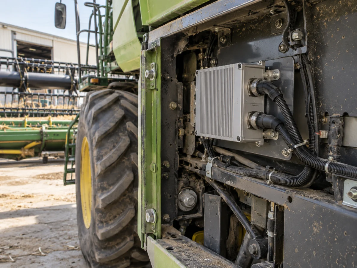
Protected electronic data acquisition module and machine cable connections in combine harvester equipment
Representative application image.
13

12/24 V supply, vibration, dust and moisture conditions

The nominal 12 V or 24 V in the vehicle does not describe all the voltages the board will see. Drooping during cranking, reverse connection and transient overvoltages are evaluated at the power input. The vehicle supply protection reference design of TI indicates that such situations require separate protection. The protection structure to be used is selected according to the electrical requirements of the machine and the test plan to be applied; The use of reference circuits alone does not ensure final product conformity.

The enclosure, PCB mounting and connector selection are assessed against temperature, vibration, dust, water and condensation conditions. We examine how the board connector is protected when the cable is under strain, whether connections could be fitted incorrectly during maintenance and where water could collect. Target conditions and validation methods are documented for the finished outdoor device. Durability cannot be inferred solely from a component's temperature rating or the protection rating of an empty enclosure.

14

4G/GNSS telemetry, local recording and software update

The telemetry unit can transmit machine ID, location, uptime, and allowed metrics to the server. Validity and timestamp of measurement GNSS are added to the record; It is not assumed that cellular connectivity will always be available on the mobile machine. Local recording when disconnected, data completion upon reconnection, and removal of duplicate records are planned. API and access permissions are also reviewed for transfer to the customer's server or integration with the existing farming platform.

If firmware over the air (FOTA) is required, the scope covers package verification, matching the device and hardware revision, and recovery from power loss or failed updates. Whether updates are permissible while the machine operates is defined. The source code and build output corresponding to the field version must be recorded. Local updates through a service tool are an alternative scope; adding internet connectivity does not automatically make updating reliable.

15

Bench testing, pilot machine trials and source file delivery

The control board is first tested on the bench with defined sensors and loads, and then on the pilot machine. The expected result for measurement limits, faulty wiring, sensor loss, communication interruption and restart is written. The tested hardware revision, software version and machine configuration are recorded. Sample PCB and electronic component assembly are only part of the prototype and production preparation in customer projects developed by VOMRO. Necessary specialist laboratory tests are planned separately.

In collaboration beginning with an NDA, project source code, schematics and PCB files, mechanical CAD, connection drawings and technical documentation are delivered at completion. The scope of the BOM, programming and build procedures, version information and test records is defined at the outset. Licences for third-party software, ISOBUS stacks and manufacturer documents are explained separately. A machine operation video, sensor/load list, power information and target functions provide a useful starting point for assessment.

How it works

A clear process from start to delivery.

Not every project looks the same; however, the measurable requirement, controlled revision, and field verification steps remain unchanged.

  1. 01

    We define the machine

    We identify the operating cycle, sensors, loads and operator requirements.

  2. 02

    We verify interfaces

    We examine electrical connection, protocol, data access and mechanical conditions.

  3. 03

    We test the pilot board

    We compare bench test results with the actual machine's operating and outage scenarios.

  4. 04

    We deliver the files

    We provide the source files, technical files and test records for the approved board and software.

Frequently asked questions

Before starting the project

The technical scope, deliverables and test plan are clarified together according to the requirements of your project.

Does the machine need to be connected to the tractor for the electronics project?

No. A self-propelled combine or forage harvester, trailed or mounted equipment, a portable electric device or a stationary crop-processing unit can be the project subject. Scope follows review of power, sensors, operator use and existing machine electronics.

As an agricultural machinery manufacturer, can we develop our own control board?

Yes. The scope of a custom board and embedded software is prepared around your sensor, load, display and communication requirements. The board's relationship with the machine, test conditions and delivery files are defined at the outset.

Can electronic display and remote monitoring be added to our existing machine?

Existing machine connections and accessible data are examined. Adding suitable sensors, developing a standalone operator display or transferring authorised data to a server may be possible. We do not assume every machine provides the same data or one ready-made module fits all models.

Will the board with CAN be compatible with ISOBUS?

Not automatically. Target ISO 11783 functions, AEF functional scope, protocol software and licences must be reviewed. Interoperability is verified for terminal, tractor and implement combinations; certification is planned separately.

Is it necessary to replace the main control unit of the machine?

In an auxiliary measurement, equipment control or telemetry project, it may not be necessary to replace the existing main control unit. The scope is determined by the machine's architecture and manufacturer documentation. Requests regarding the main safety, braking and steering functions require separate technical evaluation.

How is the cost of developing an electronic board for agricultural machinery determined?

The number of sensors and outputs, display, communication, integration with the existing machine, environmental conditions, test scope and target production quantity are evaluated. The cost of design and prototype work and subsequent board production are handled separately. Our sample PCB production and electronic component assembly service is only for customer projects developed by VOMRO.

Do you sign an NDA and deliver the board and software source files?

Yes. Before the technical details, we can work with NDA. The source code, electronic schematic, PCB and mechanical files and technical documents developed in the project are delivered at the end of the project. Third party licenses are noted separately.

Let's start with your idea

Let's talk about the product you dream of and the need you want to solve.