Joint development of camera, software and machine

Measurement and quality control systems with industrial machine vision

We develop machine vision systems that measure part dimensions and detect burrs or deformation on production lines. VOMRO designs the camera, lens, lighting, electronics, software and mechanical arrangement around your actual parts. Rule-based methods or AI are selected for the inspection task, and results are verified against reference measurements and acceptance samples.

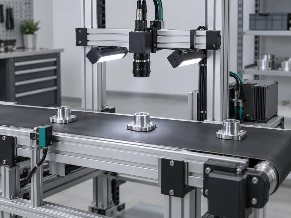
Camera, trigger sensor and image processing station that examines the metal part moving on the conveyor under controlled light
representative application
BeginningActual parts and defect samples
IntegrityOptics, software and line mechanics
AcceptanceMeasurement and classification verification

Your project, your product

Developed confidentially and delivered with source files.

We may work with a confidentiality agreement (NDA) before sharing technical details. At the end of the project, we deliver the source codes, design files and technical documents we have developed to you.

  • NDA before sharing technical information
  • Clear deliverables agreed at the outset
  • Source and technical files at the end of the project
Our confidentiality and delivery process

VOMRO engineering approach

We make the feature to be inspected visible under the production line's actual conditions.

The need for visual control arises in different ways in metal processing, plastic parts production, assembly and similar processes. Is the outer contour of a part within tolerance, are there holes, are there burrs on the cut edge, is the part bent after assembly? These questions may not be answered with the same viewing pattern. Examination direction, material, surface gloss, and motion change which feature can be distinguished in camera.

You can share the technical drawing of the part, target tolerance or defect size, line speed, and actual samples for initial evaluation. Imaging experiments are performed with accepted, defective and borderline samples; The results are compared to reference measurements. It is defined which process on the line the measurement or defect decision will turn into. VOMRO develops the electronic, software and mechanical system suitable for the customer's own production process or the machine developed.

From movement to image, from image to decision

How is a part inspected as it moves along the conveyor belt?

Select the inspection type; examine the camera's field of view, the moving part and the marked area together.

Representative image processing station where metal parts are examined on the conveyor under camera and controlled lighting
Illustrative inspection sequence
  1. 01 Part triggers capture
  2. 02 Image is taken
  3. 03 The region is evaluated

In burr mode, the area protruding from the sample part's edge is highlighted as it passes through the camera's field of view.

Representative interactive 3D simulation. Movements and signals shown do not represent actual system performance or measurement result.

Representative interactive 3D simulation · In the real project, light, optics, triggering, calibration and acceptance tests are determined together.
01

We treat dimensional measurement, burr and deformation as separate requirements

In measurements such as diameter, width, hole position or contour deviation, the element to be controlled, reference and tolerance are defined. In burr control, it is determined where and in what view the area protruding from the edge is sought. Just finding a defect and measuring its physical size are different outcomes. Which plane or surface the measurement belongs to is written in the technical requirement.

We determine whether deformation appears as an in-plane contour change, height variation or bending. If a two-dimensional view is insufficient, alternative viewing directions or 3D profile measurement are assessed. Visibility, acceptance limits and reference verification are defined for each defect type so different quality decisions are not reduced to one undifferentiated pass/fail label.

  • Measurement, reference, tolerance and control zone
  • Separate definition of edge burr and surface defect
  • Distinguishing 2D contour requirements from height and deformation requirements
02

We choose camera, lens and lighting by real part

Backlighting can highlight the outer contour; A mark or burr on the surface may require different light directions. Shiny metal, dark plastic and textured surface do not produce the same contrast. Field of view, working distance, optics and light pattern are evaluated based on the target feature. Changes in ambient light or contamination should not make the good image in the initial sample unsustainable in production.

Exposure and sensor readout matter when imaging moving parts. Area-scan and line-scan cameras are compared according to part geometry, feed conditions and inspection area. Camera resolution is not presented as measurement accuracy. On the prototype setup, we verify that the target defect can actually be distinguished and critical dimensions evaluated under defined conditions.

  • Light suitable for part surface and defect direction
  • Joint evaluation of field of view, optics and exposure
  • First imaging attempt with real samples
03

We develop mechanical fixture, trigger and electronic interfaces together

The height, orientation and vibration of the part relative to the camera are part of the measurement conditions. The camera bracket, light housing, parts guide, and fixture, if necessary, are designed with the existing line layout. Cleanliness, adjustment and service access are also taken into account. If it is desired to control the part without stopping it, it is examined with what position stability the feed can provide this.

Image capture is synchronised with trigger signals from the photoelectric sensor, encoder or line controller. Where custom electronics are needed, we develop the electrical interface between the sensor, lighting and PLC. Identity and position tracking link each result to the correct part. Changes in speed or part spacing before the sorting point are addressed rather than simply assuming a fixed time delay.

  • Brackets, fixtures, guides and mechanical guards
  • Sensor, encoder and lighting synchronization
  • Part identification and position tracking on the line
04

The inspection task determines the choice of image processing or AI

Comparing the location of a significant edge, number of holes, or defined contour can be resolved with rule-based tools. Artificial intelligence-based model development can be considered for surface defects or classification tasks with a large variety of appearances. It is not assumed that every camera project requires AI or that adding a model automatically corrects poor image.

If AI is used, sample collection, labelling, training and independent test data form part of the scope. Mixing very similar images of the same part between training and testing can overstate performance. Model version, decision threshold and operating conditions are recorded. Geometric measurement may be combined with a learned defect decision where suitable, but model confidence does not replace physical measurement accuracy.

  • Measurement and rule tools for defined geometry
  • Data and model needs according to appearance diversity
  • Model, recipe and decision threshold version tracking
05

Integration with the PLC, sorting mechanism and recording system

The image processing result, along with the measurement value and error code, can be transferred to PLC or the corresponding control software. The interface is defined for situations such as the part has been received, the examination has been completed and the result is valid. The separation mechanism receiving the command and the actual separation of the part are different events; The required verification sensor and mechanical layout are planned accordingly.

Missing images, lost triggers, communication interruptions and late results are distinguished from valid acceptance results. The inspection station complements the existing control system; machine safety functions remain within the safety controls and architecture established by risk assessment. Product recipes, user permissions, sample images and event logging are scoped around the customer's maintenance and traceability needs.

  • Result, part ID and PLC handshake
  • Separating the sorting command from verification of the physical outcome
  • Invalid inspection and connection loss scenarios
06

We attribute the precision claim to actual measurement and verification data

Converting length in pixels to physical units requires calibration appropriate to the application. Optics, camera position and measurement plane are part of this relationship. The measurement is compared to the reference method; Behavior in different locations and repeated parts is evaluated. When the position of the camera or lens changes, the relevant controls are refreshed. Resolution, repeatability and accuracy are treated as separate metrics.

In defect control, unnecessary rejection of the healthy part and acceptance of the defective part are recorded separately. Boundary samples, different production batches and actual line conditions are included in the verification plan. Performance; It is described by the data set, fault description, line condition, and software version. We do not promise a specific speed, tolerance or defect detection rate without testing. Measurable acceptance conditions are completed based on pilot findings.

  • Reference measurement and calibration plan
  • Evaluating false rejects and accepted defective parts separately
  • Acceptance result explained by data, condition and version
07

From prototype to pilot line, from confidentiality to source files

Imaging and critical functions are validated first, then electronics, mechanics and software are combined in the pilot station. Maintenance steps cover lighting and lens cleaning, recipe changes and revalidation. Prototype PCB fabrication and assembly support for the required custom board is offered only for customer projects developed by VOMRO. Scope, acceptance criteria and technical deliverables are clarified at the outset.

Before technical details, we will sign a confidentiality agreement (NDA) upon your request. Project source codes, electronic and PCB design resources, mechanical CAD files and technical documents are delivered at the end of the project. Model outputs developed under AI, training/operation information, and limits of data delivery are also listed; The license terms of third-party tools, models and libraries are explained separately. You can start the first meeting with the part drawing, samples, control purpose and existing line information.

The quote separately explains the scope of the imaging trial, camera and optical hardware, mechanical setup, software or model development, production line integration and commissioning. Equipment to be reused and third-party licences are also specified; the price of a single camera does not represent the cost of a complete inspection station.

  • Sample trial, pilot station and acceptance plan
  • NDA and customer-specific development on request
  • Source, design and technical file delivery at the end of the project

How it works

A clear process from start to delivery.

Not every project looks the same; however, the measurable requirement, controlled revision, and field verification steps remain unchanged.

  1. 01

    We define the inspection

    We examine the technical drawing, samples, error types and line conditions together.

  2. 02

    We verify the image

    We evaluate the feature to be inspected using optics, lighting, exposure and part presentation.

  3. 03

    We develop the station

    We combine electronic, software, mechanical and PLC interfaces in the pilot line.

  4. 04

    We complete acceptance and delivery

    We apply defined tests and deliver approved source and technical documents.

Frequently asked questions

Before starting the project

The technical scope, deliverables and test plan are clarified together according to the requirements of your project.

Can a camera perform measurement and burr inspection without stopping the conveyor belt?

Applicability depends on part, speed, light, optics and trigger conditions. Imaging experiments are performed with real samples; measurement and decision time are evaluated together on the pilot line.

Can you add an image processing station to an existing production line?

Yes. The integration scope is created by examining the current layout, PLC interface, part flow and separation mechanism. Control and safety responsibilities are initially separated.

Do you use AI in every quality control project?

No. With defined geometry and suitable imaging, rule-based measurement may be sufficient. The need for AI depends on appearance variation and whether the task can be validated with data.

Are the software and mechanical design source files delivered?

Source codes of the project, PCB/electronic and mechanical CAD resources and technical documents are delivered at the end of the project. File formats and delivery list are determined at the beginning; Third party licenses are disclosed separately.

Can we work with NDA before sharing technical details?

Yes. We can complete the NDA arrangements together before you share your project's technical details.

Can we start with a sample trial before committing to a complete inspection station?

A separate imaging trial can be scoped as the first stage. The samples to examine, target defect or dimension, and findings to be shared at the end of the trial are defined in advance. The results support the decision to proceed with production line integration; they do not replace acceptance of the completed production station.

Can you use our existing camera, lens or computer?

We review the existing equipment's model, connections, triggering capabilities and software access. Field of view, image quality and processing time are assessed using actual samples. Equipment whose suitability has been verified can be reused; simply being operational does not mean it is adequate for the new inspection task. Required licences and parts to be replaced are specified in the scope.

Let's start with your idea

Let's assess your part inspection requirements together.

Share the feature you want to measure or the defect you want to detect, sample parts and information about the existing line. Together, we can define the initial trial scope and the information needed for a quote.