
Technical decision guide · Conveyor and machine vision

Camera-based conveyor measurement: burr and deformation analysis

Imaging a moving part, measuring its physical dimensions and rejecting a defective part are connected but distinct tasks. A sound machine vision station is designed around inspection objectives, part presentation, optics, lighting, timing and validation. This guide explains the technical decisions and samples needed before adding a camera to a conveyor.

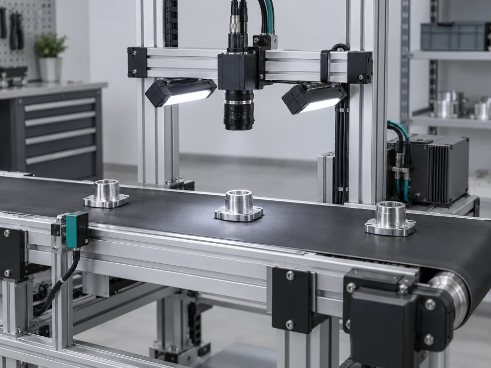
Camera imaging of a moving conveyor part, edge inspection and PLC result monitoring
representative application
first questionWhat will we check and with what reference?
ArchitectureImage, motion and decision synchronization
EvidenceIndependent samples and real line testing

VOMRO engineering approach

A fast camera alone does not result in accurate measurement or accurate separation.

Checking the outer width, finding edge burr, and measuring bending on a metal part passing through the conveyor are not the same problem. While the outer contour may be visible with a suitable backlight, a defect on the surface may require different illumination. If the height of the bend is important, a photo taken from the top alone may not be sufficient. If this distinction is not made initially, an optical or mechanical problem may be encountered that cannot be solved by camera features.

Begin with technical drawings, a defect catalogue and acceptable and defective samples. Alongside line speed, specify part spacing, orientation, height and movement to the rejection point. The following steps help prepare scope and validation plans rather than recommend a particular device or fixed performance. The selected camera, software and electronics can be assessed against project goals only when tested as an integrated station.

From movement to image, from image to decision

How is a part inspected as it moves along the conveyor belt?

Select the inspection type; examine the camera's field of view, the moving part and the marked area together.

Representative image processing station where metal parts are examined on the conveyor under camera and controlled lighting
Illustrative inspection sequence
  1. 01 Part triggers capture
  2. 02 Image is taken
  3. 03 The region is evaluated

In burr mode, the area protruding from the sample part's edge is highlighted as it passes through the camera's field of view.

Representative interactive 3D simulation. Movements and signals shown do not represent actual system performance or measurement result.

Representative interactive 3D simulation · In the real project, light, optics, triggering, calibration and acceptance tests are determined together.
01

Separate measurement, defect detection and classification objectives

The region, reference and expected output for each feature are written in the control plan. Checking the existence of a hole and measuring the position of its center in physical units are two different things. It is determined which edge will be examined for burrs, on what basis the acceptance limit will be given, and from which direction the defect is visible. In deformation, the desired feature such as contour deviation, height difference or flatness is explained.

Accepted, defective and close to the decision limit parts are collected together. Model or threshold selection cannot be started until the defect definition is clarified with the customer's quality team. The size of the smallest desired feature, measurement tolerance and surface variability are recorded. Instead of squeezing measurement and defect judgment into the same result area, physical value, validity and acceptance status are kept separate. Thus, it can be shown which requirement the pilot finding meets.

  • Drawing, control region and reference method
  • Good, defective and borderline samples
  • Distinguishing physical measurements from defect labels
02

Document part presentation and the cycle-time budget alongside conveyor speed

Rated belt speed is not a sufficient input. Speed ​​change, stop-start, smallest distance between parts and the possibility of coming together are also examined. Rotation, up-and-down movement, or vibration of the part under the camera changes the measurement plane. At this stage, it is evaluated whether a guide, carrier pocket or fixture is required. Dirt, oil and the conveyor surface are also variables of the image.

Image acquisition, transfer, analysis, result communication and travel to the rejector each take time. The system is evaluated on difficult images and consecutive parts as well as average processing time. Camera frame rate is not the validated part throughput of the line. Where the belt slips, we check how accurately a motor or shaft encoder represents actual part movement. Required layout and speed conditions are recorded for the pilot test.

  • Speed range, part spacing and position variation
  • The entire cycle time from image to separation
  • Guide, fixture and tracking of actual movement
03

Design lighting and exposure for defect visibility

Backlighting for the outer contour and hole can highlight the silhouette. Contrast is sought by changing the direction of light in case of surface burrs, scratches or bumps. Reflection on shiny surfaces can make a good part look defective or hide the actual defect. Light shape, direction, color and its relationship with optics are tested on real samples. For features that are not visible from one direction, additional viewing or a different measurement approach may be required.

Displacement of the part during exposure creates motion blur. Shortening the exposure time also affects the light budget; Increasing sensor gain can change other aspects of image quality. If strobe light is to be used, the light pulse is synchronized with the camera. Evaluation is made for ambient light, contamination of the light source, and change in part color. Settings are accepted not on the basis of a one-time good photograph, but on the visibility of the feature to be checked under defined production conditions.

  • Lighting trials suited to contours and surface defects
  • Joint control of motion blur and light budget
  • Environmental change, contamination and maintenance conditions
04

Consider global shutter and line-scan as different decision axes

Global shutter and rolling shutter describe the time pattern of exposure on the sensor. In global shutter, image lines are exposed together; Time shift in rolling shutter may cause geometric distortion in the moving part. Using a global shutter does not automatically eliminate the blurring caused by long exposure. Exposure, light and movement must again be chosen together.

Area-scan and line-scan describe how an image is formed. An area-scan camera captures an image area; a line-scan camera builds an image line by line as the material moves. Line-scan can suit continuous material or appropriately presented parts, but motion and line acquisition must match to preserve geometry. Not every fast conveyor requires line-scan. Field of view, part characteristics, optics and data flow are compared on equal terms; the sensor label alone does not establish superiority.

  • Separation of shutter type and scanning architecture
  • Further evaluation of exposure-induced blurriness
  • Camera architecture suited to the part and its motion
05

Set up trigger, encoder and part ID in the same flow

A photoelectric sensor or PLC signal can indicate that a part has entered the inspection area. Camera trigger delay, exposure and illumination timing determine the position at which it is imaged. Encoder use requires defined electrical connections, direction and counts per unit of movement. In line-scan systems, line triggering that follows speed variations helps preserve geometry, provided the motion feedback represents the actual material movement.

Capturing images at fixed time intervals does not sample equal physical distances on a variable-speed line. Likewise, a fixed delay between measurement and rejection may not select the correct part in every condition. Trigger sequence, image, result and the part travelling to the rejector are linked. Tests cover missing or additional triggers, dropped frames and resumption after stops. Preventing an earlier result from being applied to a new part after restart is an explicit acceptance scenario.

  • Part triggering and lighting/camera synchronisation
  • Relationship between sampling per unit of movement and the encoder
  • Matching trigger, image, result and physical part
06

Don't confuse pixel scale with accuracy; Separate 2D and 3D need

Calibration binds the image coordinate to the defined physical coordinate or unit of measurement. Lens distortion, angle of view, and measurement plane can affect this conversion. A relationship is established with a measurement system suitable for the reference target or application. The validity of the calibration is evaluated when camera/lens position, focus or image setting changes. How many length units a pixel corresponds to does not prove that the entire system offers the same level of accuracy.

2D contour analysis can evaluate edges and locations in the view of interest. If elevation, bulge or out-of-plane deformation is required, a laser profile or other appropriate 3D approach is examined. Geometry that is not visible from a single top view is not assumed to be measured. The uncertainty of the reference method, part position and repeat measurement results are evaluated together. It is defined under what conditions the optical and mechanical order will remain constant; Calibration and daily control operations are included in the maintenance plan.

  • Calibration plane, reference and optical layout
  • Evaluating resolution, repeatability and accuracy separately
  • Separation of contour and height requirement
07

Choose rule-based analysis or AI according to the task

Tools such as edge extraction, contour matching, distance and angle measurement can be used directly on the appropriate image and defined geometry. In the burr decision, it is determined where the edge area is and how the allowable deviation will be calculated. Not every appearance difference is a defect; Accepted production diversity is also a requirement of the algorithm. If it is possible to solve the geometric measurement with an explainable rule, it is not necessary to add AI just because a camera is used.

A learning-based model can be considered when defect appearance cannot be described sustainably through rules. We specify the class or region the model must identify, how its output is used and what happens when the result is uncertain. Rule-based localisation, measurement and AI classification can share one workflow. Model confidence is not equivalent to measurement tolerance or accuracy percentage. Options are compared on actual samples for result quality and total processing time.

  • Rule-based tools for measurable geometry
  • Requirement of AI by appearance variety
  • Separation of score, physical measurement and acceptance decision
08

Establish the validation set and calculations for false rejects and escaped defects at the outset

Images must represent variation in product type, production batch, surface, position and lighting. Labels follow the quality team's reference decisions. Training and model-selection data are separated from final evaluation data. Near-duplicate images of the same part split across these sets can produce misleading results. Separation is planned by physical part and production source, not just filename; the final test set is not repeatedly used to tune decision thresholds.

Erroneous rejection of the good part and incorrect acceptance of the defective part are separate consequences. If the ratio is to be reported, the denominator is written explicitly: the number of good parts rejected incorrectly is associated with good reference parts, and the number of defective parts missed is associated with defective reference parts. Failure types and boundary samples are also examined. Only total accuracy can conceal the escape of a rare defect. Difference with reference and repeated measurement behavior are also reported in the measurement task. All results depend on test condition, data and software version.

  • Representative samples and consistent reference labels
  • Independent evaluation and prevention of data leakage
  • False rejects, escaped defects and measurement results with explicit denominators
09

Validate the PLC and sorting fixture independently of the vision system's decision

The control interface defines states such as ready, trigger received, analysis complete, result valid and fault. Each result sent to the PLC identifies its part and validity period. An inspection failure must not appear as a passing part. The rejection mechanism may use a valve, pusher or diverter; its mechanical delay, product contact and, where possible, confirmation of rejection are tested.

Machine safety functions remain within the appropriate controls and architecture established by risk assessment, with responsibility for the camera decision defined separately. Expected line behaviour is documented for lost results, communication interruptions, rejector faults and overlapping parts. Image, part ID, recipe and version are linked in the records. The customer determines image retention scope, duration and access permissions. Pilot acceptance covers the complete workflow acting on the correct part, beyond drawing the correct box on screen.

  • Part dependent PLC handshake and valid result
  • Sorting command and verification of physical sorting
  • Outage, malfunction and overlapping parts scenarios
10

Prepare initial project package and technical deliverable

An initial assessment can start with technical drawings, inspection area, tolerances, reference measurements, samples and conveyor details. Part photographs and the existing line layout make the discussion concrete. Share camera mounting space, the PLC interface and the rejection point as well. Technical choices need not all be settled beforehand; sample imaging investigates critical uncertainties. Requested speed and measurement targets are treated as requirements to verify.

At VOMRO, we can sign an NDA at your request before technical details are shared. Project source code, electronics and PCB design files, mechanical CAD and technical documentation are delivered at completion. The handover list includes camera settings, calibration, recipes, interfaces and acceptance tests, together with developed AI outputs and the training and deployment scope. Third-party licences are stated separately. Prototype PCB manufacturing and assembly support applies only to customer projects we develop. Pilot results feed traceably into the final scope and acceptance decision.

  • Sample, drawing, speed and line interface information
  • Initial scope, testing and delivery list
  • NDA and editable technical source files at the end of the project
Match imaging and validation decisions to the inspection task
Inspection taskFirst approach to evaluatecritical variableproof of acceptance
External dimension and hole location2D image with appropriate contrast and calibrated measurementOptics, measuring plane and edge qualityComparison with reference and repeat measurements
Edge burrContour or illuminated examination from different directionsAppearance of the defect and its acceptance limitGood, defective and borderline samples
out-of-plane deformationSuitable 3D or profile-based approach that provides height informationVisibility of reference surface and geometryReference height/shape measurements
Variable surface defectRule or AI analysis after image trialData representativeness, labels and decision thresholdResults by error types in independent testing

How it works

Turn decisions into a project plan.

Not every project looks the same; however, the measurable requirement, controlled revision, and field verification steps remain unchanged.

  1. 01

    Describe the task

    Prepare the measurement, defect, sample and reference decision together.

  2. 02

    Test the imaging setup

    Evaluate lighting, lenses, exposure and part presentation using actual samples.

  3. 03

    Verify the flow

    Test the trigger, analysis, PLC result and separation on the pilot line.

  4. 04

    Record acceptance

    Document results, conditions and revisions with independent data and reference measurements.

Frequently asked questions

Before starting the project

The technical scope, deliverables and test plan are clarified together according to the requirements of your project.

Does choosing a global shutter camera completely solve the measurement problem?

No. It addresses distortion caused by the timing difference between image rows. Motion during exposure, the lens, lighting, calibration and part position still require assessment. Overall performance is verified through an integrated test.

Is a line-scan camera necessary for every high-speed conveyor belt?

No. Area-scan and line-scan are compared against part characteristics, field of view, speed, triggering and optics. In a line-scan system, line acquisition must also track actual movement.

Can every deformation be measured with a photo from above?

Contour deviation in the image plane can be evaluated; Unseen height or tilt cannot be assumed from the same photograph. Additional viewing or appropriate 3D/profile measurement is planned when necessary.

How many images and what success rate are required for defect checking?

A fixed number or ratio cannot be given without knowing the task, defect variety and production conditions. Representative samples are collected; In independent testing, faulty rejection and faulty acceptance are evaluated with separate denominators.

With which technical files does VOMRO deliver the project?

The project's software resources, electronic/PCB and mechanical CAD resources and technical documents are delivered at the end of the project. Calibration, recipe, interface and test information are included in the initially specified list; third party licenses are disclosed.

Your project, your product

Developed confidentially and delivered with source files.

We may work with a confidentiality agreement (NDA) before sharing technical details. At the end of the project, we deliver the source codes, design files and technical documents we have developed to you.

  • NDA before sharing technical information
  • Clear deliverables agreed at the outset
  • Source and technical files at the end of the project
Our confidentiality and delivery process
Let's start with your idea

Let's talk about the product you dream of and the need you want to solve.