
Connections matter as much as the probe in high-temperature measurement

Thermocouple sensors: temperature measurement with J, K, T and N types

A thermocouple determines temperature using the small voltage arising from the temperature distribution along dissimilar conductors. It is widely used in furnaces, moulds, heat treatment and test systems. Selecting a Type J or K probe alone is insufficient: connection materials, cold-junction temperature, analogue circuitry and probe placement must be considered together. VOMRO can work on integrating ready-made thermocouples into your device and developing custom multichannel temperature measurement electronics.

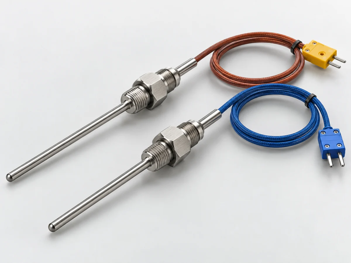
Completed thermocouple probes with closed-end metal sheaths, fittings and insulated connectors
Illustrative sensor product image.
TypesJ, K, T, N, E and other suitable types
Core requirementCold-junction compensation
VerificationProbe, cable and board together

VOMRO engineering approach

Thermocouple measurement turns a few millivolts into reliable temperature information.

Measuring a metal surface and measuring gas inside a furnace require different mounting arrangements. Sheath diameter, immersion depth, contact pressure and flow affect response. A fast bare junction may be mechanically or chemically unsuitable, while a robust sheath may respond more slowly.

This guide explains thermocouple type selection and the measurement chain. A particular probe's continuous operating temperature, insulation class and atmosphere compatibility must be verified from its manufacturer's product documentation. A letter type or general reference table does not define every operating condition of the finished probe.

The complete measurement process

From sensed quantity to usable data

  1. 01Measuring and reference junctions
  2. 02Thermoelectric voltage
  3. 03Cold-junction compensation and conversion
  4. 04Temperature for the selected type

Conceptual diagram. The actual measurement range, error budget and validation plan are defined for the application.

01

How does a thermocouple work, and why does it not directly provide temperature?

A thermocouple's two dissimilar conductors join at the measuring end; the other ends connect to the instrument. The voltage relates to the conductor pair's characteristics and temperature conditions between the ends. Reading that voltage alone is therefore insufficient to determine the measuring junction's absolute temperature. The reference connection temperature at the electronics must also be known.

Each thermocouple type has a different, nonlinear voltage-temperature relationship. Firmware must use the appropriate reference function or a validated table for the selected type. There is no single constant answer across the range to 'How many degrees is one millivolt?' A device set to the wrong type may look plausible at room temperature yet differ substantially at high temperatures, so initial commissioning checks use multiple points.

02

How are Type J, K, T and N thermocouples selected?

Type J uses iron–copper-nickel conductors, Type K nickel-chromium–nickel-based conductors, Type T copper–copper-nickel, and Type N nickel-chromium-silicon–nickel-silicon. Selection considers oxidising or reducing atmospheres, sheath material, wire diameter and intended service life alongside temperature. Type K's popularity does not make it the best choice for every process.

NIST ITS-90 tables provide reference-function ranges of −210…1200 °C for J, −270…1372 °C for K, −270…400 °C for T and −270…1300 °C for N. These are not probe operating guarantees. Cable insulation or terminals, for example, may have much lower limits than the measuring junction. Noble-metal types such as R, S and B are assessed separately for high-temperature applications.

03

How is cold-junction compensation implemented correctly?

The cold junction is not necessarily cold; it is the reference region where thermocouple conductors transition to the instrument's connection material. Its temperature is measured with a suitable sensor and included in the calculation. If the reference sensor is far from the actual terminal or beside a hot regulator, the result may be wrong even when the mathematics is correct.

Board layout examines temperature uniformity across thermocouple terminals and the effects of airflow and hot components. In a multichannel device, the assumption that all terminals share one temperature must be tested on the prototype. For VOMRO, this is a PCB and enclosure layout decision as much as a schematic decision. Acceptance may include ambient changes and self-heating with the enclosure closed.

04

Extension cable, compensating cable and polarity

Use type-appropriate thermocouple extension or compensating cable to reach the electronics. A compensating cable's equivalent thermoelectric behaviour applies within a limited temperature region; manufacturer limits must not be exceeded. Arbitrary copper-wire extensions introduce error sources if transition temperatures are uncontrolled. Correct polarity, connectors and junction locations are recorded.

Cable colour is not universal; colour codes vary between standards. Field checks rely on the applicable standard and manufacturer markings. Long routes parallel to power cables, loose or dirty connections and damp terminals are also investigated. Shield termination and grounding follow the system architecture. If sensor connections can change during maintenance, installation instructions belong in the technical delivery.

05

What is designed in a multichannel thermocouple reading board?

At low voltage levels, input offset, drift, filtering and the converter's actual noise matter. Sampling rate is not selected solely from display refresh needs; temperature dynamics, mains-noise rejection and channel count are considered together. Multiplexed architectures include settling time after channel changes in the measurement plan.

Grounded and insulated junctions create different electrical conditions. Probes touching multiple machine surfaces can develop interchannel voltage differences; channel or group isolation is planned where needed. Open-probe detection, short-circuit diagnostics, overrange and reference-sensor faults should be reported separately. Records can include channel status, timestamps and selected type alongside temperature.

06

Why are the probe and electronics checked together during calibration?

Connecting a thermocouple simulator to the input checks the reading circuit; it does not by itself reveal physical probe mounting errors or ageing. To assess the full chain, compare the probe with a reference thermometer in a suitable temperature environment. Differences between displays should not be assigned directly to sensor error without checking immersion depth, thermal equilibrium and temperature distribution.

The acceptance plan specifies target points, reference uncertainty, waiting time, ambient temperature and cable used. A thick probe insufficiently immersed in a furnace may read differently from the target region because heat conducts along it. An ageing thermocouple's error may not remain a constant offset. Maintenance intervals are initially estimated and updated from field and comparison records; no fixed calibration interval is asserted for every application.

07

Information that makes a thermocouple project ready for quotation

For example, a multizone mould monitor compares mounting space, surface temperature and required response before putting the same probe at every point. It defines whether channels are read simultaneously or at intervals, cable distances and existing PLC connections. This is an example project approach, not a ready-made product feature or a claim of a completed reference project.

Start a discussion with VOMRO by sharing channel count, type, minimum and maximum temperatures, target error, cable length and data output. Custom electronics, firmware, logging interface, enclosure and production test setup can be separate deliverables. Sensor supply and custom probe manufacture are not treated as the same scope; a suitable specialist probe manufacturer's solution can be integrated where needed. Technical source delivery and acceptance records are clarified in the project contract.

Initial type comparison. Ranges are NIST reference functions, not operating limits for a particular probe.
TypeReference-function rangeSelection consideration
J−210…1200 °CAtmosphere compatibility of the iron conductor and sheath
K−270…1372 °CAtmosphere, cycling and long-term stability
T−270…400 °CLow-temperature requirements and mechanical construction
N−270…1300 °CSuitable probe and cable selection at high temperatures
R / S / BSeparate reference function for each typeNoble metals, contamination and cost

How it works

A clear process from start to delivery.

Not every project looks the same; however, the measurable requirement, controlled revision, and field verification steps remain unchanged.

  1. 01

    Examine the measurement points

    We define the environment, temperature cycle, probe mounting and channel requirements.

  2. 02

    We design the chain

    We match the type, cable, terminals, cold junction and electronics architecture.

  3. 03

    Test the prototype

    We measure internal enclosure temperature, channel interactions and fault notifications.

  4. 04

    Record the comparison

    We document reference acceptance points and the delivered calibration arrangement.

Frequently asked questions

Before starting the project

The technical scope, deliverables and test plan are clarified together according to the requirements of your project.

Can a Type K thermocouple replace Type J?

The instrument must be configured for the correct type, and cable, connector, range and process compatibility must be verified. Changing the probe alone does not ensure correct temperature measurement.

Is the upper limit of a Type K thermocouple always 1372 °C?

No. 1372 °C is the upper limit of the NIST reference function. A real probe's continuous operating limit depends on wire diameter, sheath, insulation and atmosphere; its product documentation governs.

Can a board without cold-junction compensation be used?

A special arrangement is possible if the reference connection temperature is known by another method and included in the calculation. Ignoring reference temperature in a changing environment creates measurement error.

Can ordinary copper cable extend a thermocouple?

The general solution is type-appropriate extension or compensating cable. Copper transitions are only considered in a specific architecture with controlled temperatures and reference conditions; arbitrary splices should not be made.

Is a thermocouple or Pt100 more suitable?

Temperature range, target uncertainty, mechanical durability, response and cost are assessed together. Thermocouples are candidates for broad or high-temperature ranges, but are not automatically superior for every measurement.

Can one board read different thermocouple types?

This may be possible with suitable inputs and software. Each channel's type, conversion, cold-junction arrangement and diagnostics are defined; supported types and ranges are verified during acceptance testing.

Your project, your product

Developed confidentially and delivered with source files.

We may work with a confidentiality agreement (NDA) before sharing technical details. At the end of the project, we deliver the source codes, design files and technical documents we have developed to you.

  • NDA before sharing technical information
  • Clear deliverables agreed at the outset
  • Source and technical files at the end of the project
Our confidentiality and delivery process
Let's start with your idea

Build your multichannel temperature measurement on the right foundation

Share probe type, channel count, temperatures and cable distance; together, we can define the measurement board, cold-junction arrangement and software scope.