
Engineering for machinery and production systems

Custom electronics and control systems for industrial automation

We develop functions that standard modules cannot provide for automation companies and machine manufacturers. Custom control boards, sensor interfaces, embedded software and operator displays for industrial automation systems are addressed within one project plan. We define connections to the existing PLC and control cabinet, then validate the prototype in the machine's actual operating cycle to prepare it for production.

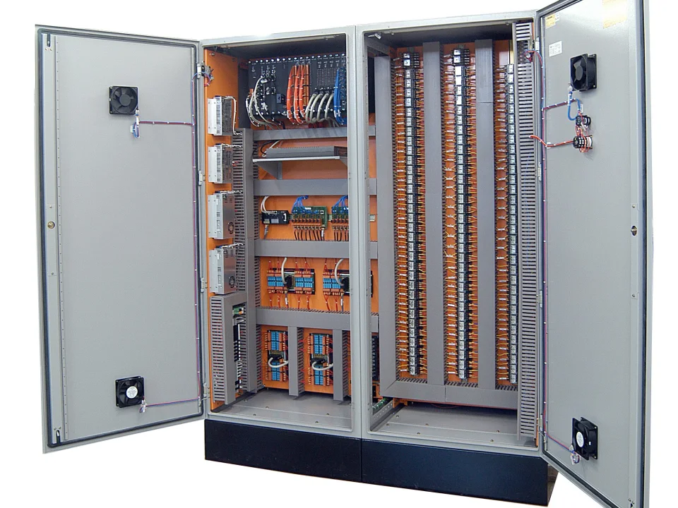
Open industrial control cabinet containing a PLC, electronic modules, terminal blocks and wiring
Industrial control cabinets and electronic interfaces
CustomerMachine manufacturer and integrator
InterfaceSignaling, control and communication
DeliverySource files and technical documentation

Your project, your product

Developed confidentially and delivered with source files.

We may work with a confidentiality agreement (NDA) before sharing technical details. At the end of the project, we deliver the source codes, design files and technical documents we have developed to you.

  • NDA before sharing technical information
  • Clear deliverables agreed at the outset
  • Source and technical files at the end of the project
Our confidentiality and delivery process

VOMRO engineering approach

The decision to use a custom control board starts with the machine's actual operation.

Monitoring product passage through a packaging machine, capturing repeatable data from a dosing unit, or combining equipment using different protocols do not create the same electronic need. Cycle time, number of inputs, measurement quality, installation space and service format vary with each project. Therefore, the first output in automation supporting project development is not the processor selection, but the requirement list explaining which behavior the machine should display in which event.

VOMRO evaluates the existing PLC and the electrical control panel structure, mechanical system and operator's working style together. There is a clear distinction between the functions that the dedicated board will undertake and the tasks that will remain with the existing controller. When comparing offers, these task limits, acceptance tests and source files to be delivered should be examined within the same scope. We transform the customer's process information into a signal table, status flow and tests that can be verified on the machine.

01

When does a custom board alongside a PLC make sense?

If an off-the-shelf PLC expansion module meets the requirement, it can shorten development time. Custom electronics are considered when a repeated machine family needs a common I/O arrangement, a custom sensor interface, a compact installation or a communication function unavailable in standard modules. The decision is based on more than the board's unit cost; design effort, assembly, testing, spare parts and field maintenance also count.

For example, in a machine whose main movements are controlled by a PLC, the custom board may handle measurement and communication only. In another project, a defined operating sequence may run in the board's embedded software. Safety-related functions and control responsibilities are clarified with the relevant system teams at the outset. This defines when the new unit operates independently and when it waits for the main controller's decision.

  • Comparison of ready module and custom design with the same scope
  • Reuse and revision plan according to machine family
  • Clear definition of control and safety responsibilities
02

We design industrial I/O and sensor interfaces according to the field

A 24 V digital input, PNP/NPN sensor, 0–10 V voltage signal, 4–20 mA current loop and encoder connection require different input circuits. Each channel's electrical type, measurement range, sampling needs, cable length and connection arrangement are defined. Design depends on precision and calibration for analogue measurements, frequency and minimum pulse width for pulse inputs, and load current and switching behaviour for outputs.

The measurement circuit's operation alongside motors, contactors and valves in the control cabinet is assessed. Supply variations, possible miswiring, reverse polarity, isolation requirements and cable-borne disturbances are incorporated into the hardware architecture. Connector pin assignments are considered alongside the machine's wiring harness. A disconnected sensor or invalid reading is presented in software and on the operator display as a state distinct from normal process data.

  • Analog measurement, digital input and pulse counting
  • Driver and output interfaces suitable for the load
  • Supply, protection, isolation and service access
03

Meaningful integration of Modbus, CAN and machine data

An RS485 connection alone does not make devices communicate correctly. For Modbus RTU or Modbus TCP, addresses, register maps, data types, scaling and write permissions are defined. A CAN-based system also requires an application protocol and message dictionary. A sensor reading's unit, validity and update time matter as much as its numerical value; carrying different units under the same name can cause integration errors.

In projects where machine data will be transferred to the server, local gateway, Ethernet, Wi-Fi or cellular connection are evaluated according to field conditions. Sending a command, receiving it by the device, and physically executing it are separate events. Confirmation and outcome information should demonstrate this distinction. How to keep records when the connection is lost and how to handle old commands when reconnected is also added to the interface documentation.

  • Protocol converter and custom gateway development
  • Data dictionary, timeout and error states
  • Local logging, server API and command result tracking
04

We verify industrial automation software with real machine

Control software defines more than the normal operating cycle. It also covers startup, parameter loading, sensor readiness, stopping and restart after faults. If recipes or machine parameters are stored, their valid ranges and when changes take effect are specified. The software version, board revision, device identity and fault history are made accessible for servicing.

The operations that the operator can perform on the button, indicator, screen or HMI interface are separated from the settings that the maintenance team can access. Instead of a vague error code, it is shown which input is not expected and which check can be made. The position of the screen and buttons is tested along with the mechanical layout. Usage details such as gloves, viewing angle and working distance contribute to the easy use of a technically correct system in the field.

  • State machine and behaviour after interruptions
  • Parameter, recipe and service interfaces
  • Error and process information that the operator can understand
05

We adapt the electronic circuit board to the mechanical structure of the machine

Board size, connection direction and mounting holes are not details determined at the final stage. Use in the electrical control cabinet, mounting on the machine body or a standalone interface box creates different mechanical requirements. Cable bending space, ventilation, sequence of removal during service and access to the programming connection are controlled in the internal layout. If necessary, the board, connector and wiring harness are evaluated together on the 3D prototype.

Parallel progress of electronic prototype development and mechanical design reduces pre-production repetitions. The layout, labeling and mechanical fixing that prevents mixing of similar connectors also serves the maintenance process. Dust, humidity, vibration or temperature targets are derived from usage conditions; The sample and test with which these goals will be verified are shown in the project plan.

  • CAD layout suitable for electrical control panel, box and machine
  • Wiring harness, connector and mounting access
  • Prototype evaluation according to real use environment
06

From first prototype to pilot machine and production testing

On the first board, the power supply, inputs, outputs and communication are brought up separately. Scenarios are then tested with actual sensors and loads. Power loss, communication loss, sensor disconnection and parameter limits are included in the test list. As the cycle and wiring are validated on the pilot machine, findings are recorded against the hardware revision and software version. Acceptance means performing the defined task under the specified conditions, not merely powering on.

Production preparation includes the bill of materials, sourcing alternatives, programming steps and functional tests. Design validation and inspection of each manufactured board are separate processes, with test points and fixture access planned accordingly. Rapid prototype PCB fabrication and assembly support are provided only as part of customer projects developed by VOMRO; we do not offer general PCB fabrication or assembly orders outside those projects.

  • Acceptance tests matched to requirement
  • Pilot integration and traceable revisions
  • BOM, programming and production control plan
07

Confidentiality, source delivery and the initial project discussion

At your request, we sign a non-disclosure agreement (NDA) before you share the machine's operation and proprietary technical details. The customer project is not turned into VOMRO's own product catalogue. Project source code, electronic and mechanical design files and technical documents are delivered at completion. Editable source formats, build environment and deliverables list are defined at the outset; third-party component licence terms are explained separately.

For the first conversation, you can share what the machine does, the existing PLC or controller, the sensor and load list, the supply conditions and the function you want to add. The target production quantity, layout limit and access to the pilot machine also clarify the scope. If the drawings are not ready, we create the requirements together based on the usage scenario. The proposal is prepared so that the development deliverables and how they will be accepted are visible.

  • NDA on request before technical details are shared
  • Source, EDA/CAD and technical document delivery
  • Concrete project scope via signal list and pilot

How it works

A clear process from start to delivery.

Not every project looks the same; however, the measurable requirement, controlled revision, and field verification steps remain unchanged.

  1. 01

    We define the function

    We determine the task, interfaces and acceptance conditions that the machine requires.

  2. 02

    Develop the system

    We design the board, embedded software, mechanical layout and operator interaction together.

  3. 03

    We confirm with the pilot

    We evaluate normal operation and outage scenarios with real equipment.

  4. 04

    We prepare for production

    We deliver the sources, production files and test documents of the approved revision.

Frequently asked questions

Before starting the project

The technical scope, deliverables and test plan are clarified together according to the requirements of your project.

Are you developing custom boards that work with our existing PLC system?

Yes. We develop boards that complement the existing PLC for tasks such as sensor interface, industrial I/O, special measurement or gateway. Electrical connections, protocol and control responsibility are defined at the beginning.

Can the same board be used in a machine family?

Hardware options or software parameters can be planned by examining common functions and model differences. The connections and acceptance tests of each variant are also defined; It is not assumed that the same board will fit every machine.

Can the scope cover only custom electronics and embedded software?

Yes. We can share work with your own automation and mechanical team. Connection drawings, data dictionary, responsibilities and integration tests are written into the project scope.

Are source files and designs delivered?

Project source codes, editable design files and technical documents are delivered at the end of the project. File formats and delivery list are determined at the beginning; third party licenses are noted separately.

Can we work with NDA before sharing technical details?

Yes. We can complete the NDA arrangements together before you share your project's technical details.

Let's start with your idea

Let's talk about the product you dream of and the need you want to solve.