
Technical decision guide · Automation

Custom circuit boards for automation: when are they needed?

A custom electronic circuit board may be required to add a new sensor to a machine, to make different devices talk, or to collect a reused function in a single unit. The right decision is made by comparing the possibilities of PLC and ready-made modules with the project requirements. This guide describes the technical framework that can be prepared before the bid.

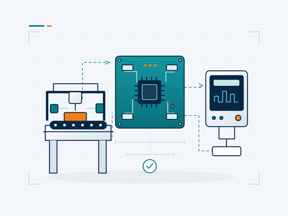
Technical representation of sensor and communication connections between existing automation and custom electronic circuit board
Conceptual technical demonstration · Technical decision guide · Automation
DecisionOff-the-shelf module or custom board
InputSignal and interface list
ResultMeasurable development scope

VOMRO engineering approach

First define which gap you will close.

A good starting sentence for a custom design describes the need rather than “we want a board”: “We will transfer the value from this sensor to the current controller; we will measure it in the following range; we expect this behavior when the connection is disconnected.” Such a definition allows you to evaluate the work to be done without tying it to a selected processor. Starting with board size or component selection while the scope is still unclear may lead to overlooking the real need.

Existing PLC inputs, expansion modules, ready-made converters and custom electronics option should be taken together for comparison. In addition to the initial investment, cabling, assembly, service, software maintenance and remanufacturing are also taken into account. The decision criteria for a single field solution and a unit to be used on different machines may not be the same.

01

1. Base the custom board decision on its application and the number of units required

If a ready-made module provides the measurement function and fits the mechanical layout, it can reduce development work. A custom board becomes more valuable when custom sensor excitation, nonstandard processing, many similar connections or a machine-specific form factor are required. Reusing the function across machines also changes how the design effort is evaluated.

Compare alternatives with the same scope. Do not add the connector and box cost to one option and look only at the price of PCB in the other. Programming, testing, spare parts, commissioning and subsequent revisions should be included in the same evaluation. If technical uncertainty is high, a useful intermediate step is to validate critical sensor or communications functionality in a small assembly before designing the entire board.

  • Write the concrete function that is missing in the ready-made solution
  • Specify reuse and target production quantity
  • Compare the full scope, including installation and maintenance
02

2. List the inputs and outputs with their electrical specifications

Saying that four sensors will be connected is insufficient for design. Record each sensor's type, output range, supply needs, sampling frequency and cable length. Pulse inputs require defined frequency and minimum pulse width; analogue inputs require accuracy, range and calibration methods. Outputs must specify load type, operating current and switching method.

Assess expected variations and startup behaviour as well as the control cabinet supply's nominal value. Effects from motors, valves and relays are examined alongside measurement sensitivity. Connector layouts that reduce miswiring, test points and programming access belong in the initial design. ST's hardware development documentation is an example reference for considering power, reset and debug connections together.

  • Signal range, power supply and cable length
  • Measurement accuracy and sampling requirement
  • Load, connector, test and service connections
03

3. Distinguish the RS485 connection from the application protocol

RS485 defines the electrical communication layer; it alone does not determine the data addresses or the meaning of the commands. If an upper protocol such as Modbus will be used, device addresses, register map, data types, scales and read/write permissions are defined separately. In order for two devices using the same cable to communicate, these details must be the same on both sides.

Physical network design examines cable routes, line ends, branches and termination. Ground potential differences between units on separate supplies determine isolation needs. TI's RS485 design guide details these electrical decisions. Keeping the connection drawing and message dictionary separate helps distinguish wiring faults from data-interpretation problems in the field.

  • Line topology and electrical connection drawing
  • Dictionary of address, data type, unit and scale
  • Timeout, retry and error codes
04

4. Define interruption behaviour alongside normal operation

The status of the outputs when the device is turned on, when the first valid measurement will occur, and how the saved parameters will be loaded must be determined. When communication is interrupted, options such as preserving the last command, turning off the output, or local operation are evaluated according to the needs of the application. Safety-related tasks and control responsibility are clarified with the relevant system experts.

Receiving the command and executing it are different events. The resulting information returned to the server or PLC should indicate this distinction. Timestamp or validity information can be added to prevent old data from being presented as valid data in the measurement. Software version, device ID and error logs also make visible information that is difficult to reproduce during the service process. Each of these behaviors can be translated into acceptance testing.

  • Power-up, low supply voltage and restarting
  • Sensor disconnection and stale-data behaviour
  • Command acceptance, execution and result recording
05

5. Clarify testing and source delivery before requesting a quote

The acceptance checklist should state how each requirement is tested. Examples include comparing sensor inputs at defined points, checking the expected response when the communication cable is removed and verifying parameter retention after power returns. Match results to hardware revision, software version and test conditions so later changes can be assessed against that record.

In VOMRO projects, source code, design files and technical documents are delivered at the end of the project; The list and file formats are determined initially. Interface description, programming information and test conditions are clearly written in this list. Third party licenses are noted separately. Sample PCB and electronic component assembly support are only for customer projects developed by VOMRO. You can come to the first evaluation with a signal table, current system information and basic operating scenario.

  • Acceptance testing paired with requirement
  • Revision, release and test condition recording
  • List of source, design, interface and production files

How it works

Turn decisions into a project plan.

Not every project looks the same; however, the measurable requirement, controlled revision, and field verification steps remain unchanged.

  1. 01

    Write the need

    Describe the missing function and usage scenario in the ready-made system.

  2. 02

    List interfaces

    Bring together signals, loads, protocols and mechanical connections.

  3. 03

    Define acceptance

    Determine how each function will be validated and under what conditions.

  4. 04

    Evaluate the scope

    Discuss development, prototyping, testing and source delivery together.

Frequently asked questions

Before starting the project

The technical scope, deliverables and test plan are clarified together according to the requirements of your project.

Does the custom electronic circuit board replace PLC?

Not every project has such a goal. The board can complement the existing PLC by taking on a specific sensor reading or communication task. Control and safety responsibilities are clearly determined prior to design.

Will every device with RS485 work with Modbus?

No. RS485 is the electrical layer. Support for Modbus, message format, addressing and data map should also be verified. The same connection type does not guarantee compatibility at the application level.

What should we prepare to clarify the project proposal?

The current control system, sensor and load list, supply conditions, communication expectation and basic usage scenario are a good start. Size, production quantity and acceptance tests also clarify the scope.

Your project, your product

Developed confidentially and delivered with source files.

We may work with a confidentiality agreement (NDA) before sharing technical details. At the end of the project, we deliver the source codes, design files and technical documents we have developed to you.

  • NDA before sharing technical information
  • Clear deliverables agreed at the outset
  • Source and technical files at the end of the project
Our confidentiality and delivery process
Let's start with your idea

Let's talk about the product you dream of and the need you want to solve.