
Technical decision guide · From electrical control panel to PCB

How to move from a PLC and relay cabinet to a custom PCB

For machine manufacturers building similar control cabinets for each order, a custom board offers an opportunity to rethink the production architecture. Decisions must consider functions, field connections, safety boundaries, maintenance and total cost before deciding to remove the PLC. This guide helps prepare the technical documentation for moving from an existing cabinet to a verified customer-specific board.

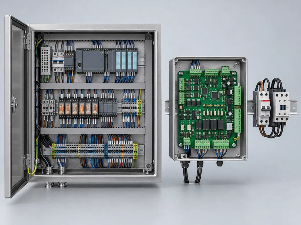
Illustrative comparison of an existing PLC and relay control cabinet with a machine architecture that combines control and I/O functions on a custom PCB
representative application
InputCurrent electrical control panel, program and I/O
DecisionFunction limit and total cost
AcceptanceBench + pilot + production test

VOMRO engineering approach

Moving to a PCB is a system design decision before it is a layout change.

A control cabinet uses a PLC, relays, timers, converters, a power supply and terminals to perform a defined task. A custom board can combine some of these functions, but it does not automatically inherit every capability of the existing devices. Input protection, software changes, service diagnostics, isolation and production testing must be defined again. A smaller board alone does not demonstrate a successful transition.

For VOMRO, projects repeated ten or more times a year may warrant this initial assessment. Volume alone does not determine economic viability. Design changes, labour, production time, maintenance arrangements and development costs must be considered together. The following steps help you assess the technical and commercial implications of your own system; they are not a circuit or safety design prescription suitable for every control cabinet.

01

First, create an up-to-date record of the cabinet that actually operates the machine

Check that the electrical schematic, PLC program, HMI project and bill of materials represent the same version. A relay added on site, a replaced sensor or a manually installed jumper may be missing from the schematic. Compare cable labels, power supply groups, terminal order and device models with the actual machine. An NDA can be agreed before technical information is shared; permission to use and modify the necessary files must also be clarified.

Record the normal production cycle and less frequent conditions: setup, product changeover, stopping, maintenance and restarting. The program alone may not explain why a setting has a particular value or which mechanical requirement a delay addresses. Capture the knowledge of operators and maintenance staff in the requirements document. The first deliverable is a verifiable description of existing behaviour, rather than a board schematic.
02

Distinguish where the PLC should remain, where an auxiliary board is sufficient and where a custom controller is needed

If the PLC program changes frequently for different customers, an established ecosystem familiar to the field team may offer an advantage. An auxiliary board alongside the PLC may be sufficient for a specific sensor measurement or protocol conversion task. A more comprehensive custom controller can be considered for a machine family with a stable control sequence and I/O arrangement. These options create different development and maintenance responsibilities and should not be treated as the same quotation item.

Prepare a task table instead of marking every cabinet component as something to move onto the board. Show where standard power supplies, motor drives, contactors, circuit breakers and safety equipment fit within the system. Compare assembly, spare parts and service access when choosing between a single board, modular boards or a hybrid solution with a PLC. The level of integration should follow the actual operating constraints.

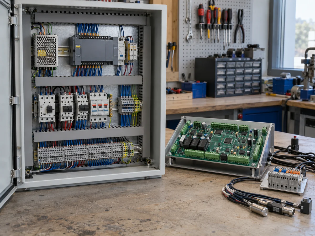
A custom PCB prototype beside an industrial control cabinet, being compared against its connection requirements
Representative application image.
03

Expand the I/O list from channel counts into electrical requirements

For each input, record the sensor model, PNP/NPN or analogue output type, power supply, expected range, cable and event duration. A 24 V digital input, an encoder, a 0–10 V input and a 4–20 mA interface require different circuits. Pulse counting requires the shortest pulse duration and highest frequency; analogue measurement requires accuracy, filtering and a calibration method. A disconnected sensor or an out-of-range value must be distinguished from normal operating data.

For outputs, specifying only the load's nominal current is not enough. Assess inrush current, inductive energy, switching frequency and fault behaviour for each coil, valve, relay or external drive input. Diagnostic features in a protected switching IC can provide information to the software, but they do not independently fulfil product safety responsibilities. The interface table should also show which power supply group serves each channel and which connections are shared.

04

Preserve the responsibilities of switchgear, electrical safety and functional safety systems

The presence of a control output on a board does not establish that it is suitable for a safety function. The architecture required for emergency stops, door interlocks, safe stopping and similar tasks is determined by the relevant risk assessment. Any required safety PLCs, safety relays, contactors and drive safety functions retain their roles in that architecture. Adding a function with the same name to general-purpose firmware does not replace a certified safety function.

Machine electrical equipment and low-voltage control assemblies may fall under different product or system scopes. References such as IEC 60204-1 and, where applicable, the IEC 61439 series inform the assessment; the applicable standards and tests are determined for the particular product. Protective earthing, overcurrent protection and the mains section layout are addressed with the system team. Moving part of a control cabinet design onto a PCB does not automatically establish conformity of the final machine.

05

Plan isolation, EMC and thermal conditions around the board's actual layout

In a system containing motors, contactors and long field cables, assess the power input, signal protection, return currents and isolation requirements together. ST's industrial I/O architecture separates responsibilities on the processor and field sides. PCB layout and the connections of the completed device are just as important as selecting suitable isolation components. No single clearance or creepage distance in millimetres applies to every product.

Assess insulation coordination using the voltage, overvoltage conditions, pollution, materials and applicable product requirements. The test plan determines which ESD, electrical fast transient/burst, surge and emissions tests are required. Test results for a component or reference board do not constitute approval of a new PCB. Evaluate thermal behaviour with simultaneously operating outputs, the enclosure, ambient temperature and wiring; tests requiring a specialist laboratory are planned separately.

06

Define firmware requirements instead of simply copying the PLC program

Convert the operating sequence, counters and timers into a state flow. Define output states at startup, loading valid parameters, sensor readiness, recovery after faults and restarting. Do not assume that a sequence that works correctly within a PLC scan will have identical timing on another processor architecture. Set measurable targets for critical timing and establish an appropriate task and event structure in the software.

For Modbus/CAN communication with an HMI, PLC or server, specify data types, scaling, permissions and freshness. Verify receipt of a command separately from its physical execution. Retaining settings through power loss, software updates and compatibility with existing machines are service requirements. Record the board revision, firmware version and machine model together. Logs and fault records should help maintenance staff diagnose a channel or connection.

07

Separate bench testing, pilot machine testing and production testing of every board

At the bench, test known sensor stimuli, real loads and communication scenarios. Write down expected results for low and high input values, sensor loss, connection faults, restarts and parameter limits. Define the scope of design validation according to product risks. Test records should identify the board revision, program, equipment and conditions together; simply stating that the board worked does not replace an acceptance report.

On the pilot machine, compare the existing cabinet and the new arrangement using the same tasks and conditions. Check cycle performance, quality, operator actions and service access. Resolve differences before wider production and prepare a rollback plan if needed. Separately develop a production fixture to check programming, identity, I/O and communication on every new board. Prototype PCB fabrication and assembly support is provided only as part of customer projects developed by VOMRO.

08

Base the financial decision on annual volumes, changes and servicing costs

For the existing solution, include cabinet layout, cable preparation, assembly, programming, checking and rework time alongside PLC and relay prices. For the board option, add development, prototypes, EMC and other tests, firmware maintenance, production fixtures and spare boards. Compare equivalent functionality and acceptance scopes. Switchgear and safety equipment that remain in the system alongside the board cannot be excluded from the calculation.

Annual production of ten or more units is only a starting point for discussion. Expected repeat production over the product's life, the number of models, component availability and change frequency all affect the break-even assessment. Apparent component savings may be offset by new model revisions or maintenance demands. No savings percentage is quoted without design and production quotations. At the end of the pilot, update the initial assumptions using actual assembly and testing times.

09

Include a delivery list that supports production and maintenance in the specification

Example scope: 'The defined machine model's standard control sequence and sensor interfaces will run on a custom board; the specified power and safety equipment will be retained; data exchange with the existing HMI and comparative acceptance testing on the pilot machine will be completed.' This is an example for preparing a specification, not a customer reference. Add machine variants, sensor/load tables, drawing versions, target volumes and acceptance criteria to this description.

At your request, VOMRO works under an NDA before technical information is shared. Source code developed for the project, editable schematic/PCB source files, mechanical CAD within scope and technical documentation are delivered at project completion. The delivery list includes the BOM, manufacturing outputs, connection diagrams, build/programming instructions, configuration and test records. Licences for existing PLC/HMI tools, manufacturer documentation and third-party software are explained separately; unconditional transfer of all rights is not assumed.

  • Current cabinet, program and model/variant list
  • I/O, loads, interfaces and functions to retain
  • Bench, pilot and production acceptance criteria
  • Source files, manufacturing and service documents, and third-party licence list
Assess cabinet functions separately when deciding on a custom PCB
TaskPossible architectureClarify firstCheck during acceptance
Sensors, measurement and auxiliary interfacesCustom I/O or communication board alongside a PLCSignals, units, speed, cables and data mapReference values, faults and timeouts
Stable machine control sequenceCustom control board and firmware where the requirements allowStates, parameters, variants and maintenanceComparison of cycle and fault behaviour in the old and new systems
Power and switchgear connectionsSuitable power equipment and a designed board interfaceVoltage, current, load, protection and thermal limitsDefined loads, assembly and electrical validation
Machine safety functionsSafety architecture determined by risk assessmentRequired safety PLCs, relays, drives and responsibilitiesRelevant safety validation and system acceptance

How it works

Turn decisions into a project plan.

Not every project looks the same; however, the measurable requirement, controlled revision, and field verification steps remain unchanged.

  1. 01

    Document existing behaviour

    Match the current schematic, program and actual machine to the same version.

  2. 02

    Separate tasks and interfaces

    Define the roles of the custom board, standard controller, power components and safety components.

  3. 03

    Define pilot acceptance

    Make normal operation, faults, interruptions and maintenance conditions comparable.

  4. 04

    Clarify costs and delivery

    Include development, production, maintenance and source files in the same project plan.

Frequently asked questions

Before starting the project

The technical scope, deliverables and test plan are clarified together according to the requirements of your project.

Does converting a cabinet to a PCB always mean removing the PLC?

No. The PLC can remain while only sensor measurement, I/O or communication functions move onto a custom board. A custom controller can also be considered for a stable control sequence. The appropriate scope depends on how the machine operates and the maintenance requirements.

Is a custom board always economical after ten units?

No. Ten or more repeat units per year is a starting point for an initial assessment. Development, validation, assembly, testing, maintenance, model changes and production expectations must be calculated on a comparable basis. There is no universal economic threshold or savings rate.

Can switchgear and safety equipment also move onto the board?

Electrical requirements and risk assessment determine where each circuit belongs. A general-purpose PCB does not automatically fulfil the functions of required fuses, contactors, safety PLCs or other safety systems.

Can we work under an NDA and receive the source files?

Yes. We can work under an NDA before technical information is shared. Code, schematic/PCB and mechanical source files developed within the project, together with technical documentation, are delivered at project completion. Third-party licensing and access conditions are stated separately.

Your project, your product

Developed confidentially and delivered with source files.

We may work with a confidentiality agreement (NDA) before sharing technical details. At the end of the project, we deliver the source codes, design files and technical documents we have developed to you.

  • NDA before sharing technical information
  • Clear deliverables agreed at the outset
  • Source and technical files at the end of the project
Our confidentiality and delivery process
Let's start with your idea

Let's talk about the product you dream of and the need you want to solve.