
Machine builder-specific control electronics

Circuit board and control system development for textile machinery

We develop electronics tailored to your product's needs, from yarn winding and fabric feed monitoring to auxiliary textile machinery and finishing and drying data. VOMRO designs the control board, operating software, user display and mechanical layout around your machine's workflow.

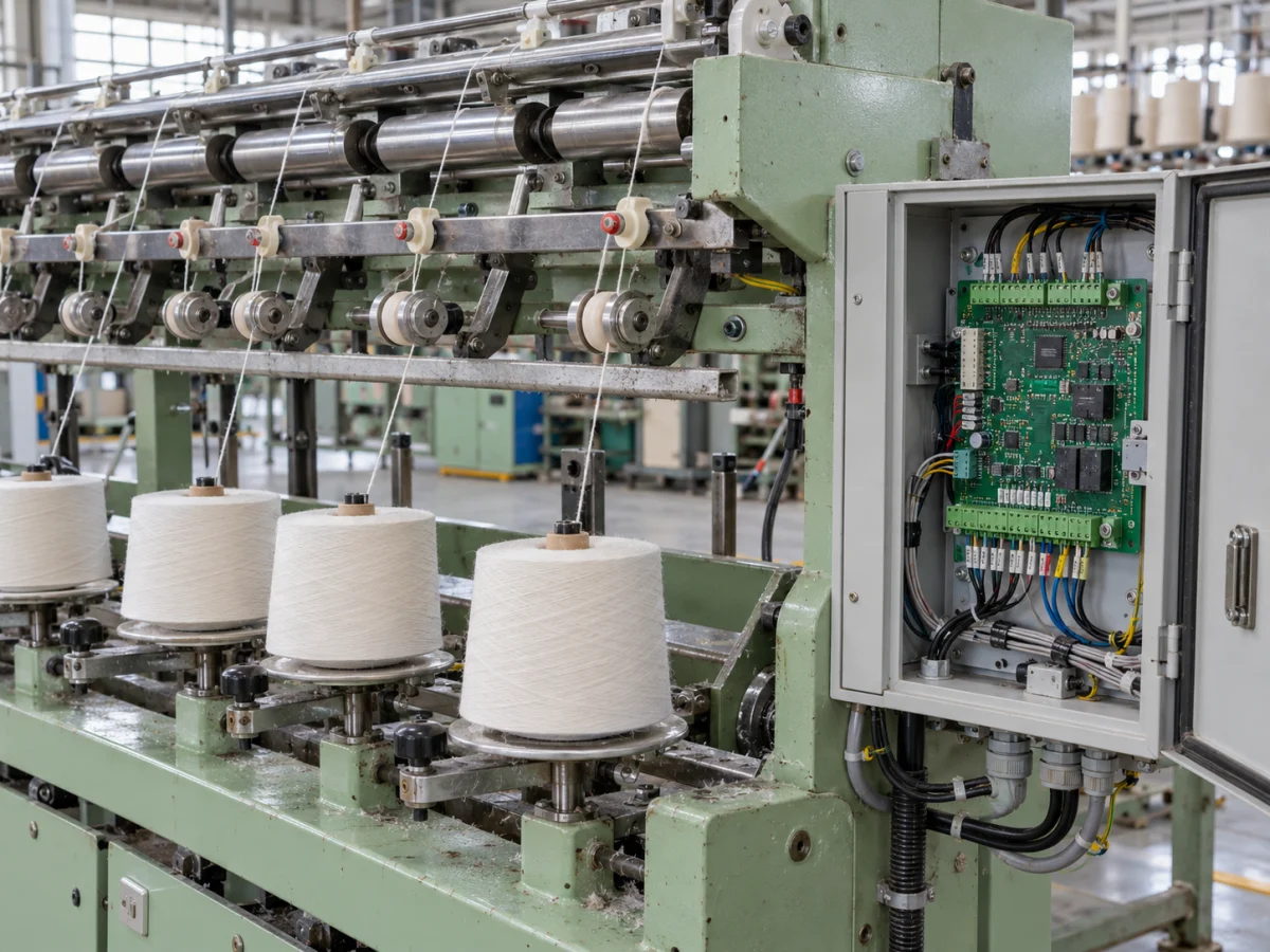
Custom electronic control board and field connections integrated into a yarn feeding and winding machine
Representative application image.
CustomerTextile machinery and equipment manufacturers
TogetherSensors, control board, software and display
DeliverySource, design and test files

Your project, your product

Developed confidentially and delivered with source files.

We may work with a confidentiality agreement (NDA) before sharing technical details. At the end of the project, we deliver the source codes, design files and technical documents we have developed to you.

  • NDA before sharing technical information
  • Clear deliverables agreed at the outset
  • Source and technical files at the end of the project
Our confidentiality and delivery process

VOMRO engineering approach

We define the machine's task before defining its control board.

Detecting a yarn break in a winding machine, monitoring fabric feed and recording process data in a drying unit are different electronic requirements. We begin textile machine control board design by separating these tasks. Together, we define which settings the operator adjusts, which events the board detects and under which conditions the machine waits.

We can work with manufacturers developing a new device for their own brand, companies adding features to existing machines and teams designing an auxiliary module for repeat production. The project focuses on creating a design for your company. Drives, PLCs, sensors and mechanical structures to be retained are examined at the outset, and electronics, firmware and mounting requirements are prepared within a shared scope.

01

Design for new machines, auxiliary modules and model families

We clarify whether the custom board will manage the entire machine, a particular group of sensors or the operator display. A standalone controller may suit an auxiliary machine for yarn transfer, bobbin winding, length counting or sample preparation. On a larger line, a custom measurement or data acquisition board working with the existing PLC may be considered.

If shared electronics are intended for multiple models, variations in inputs, motors, display options and mechanical dimensions are listed. We determine which differences can be accommodated through software settings and which require a different board or cable. This takes the prototype beyond a single demonstration board towards a product architecture suited to the manufacturer's model range and service arrangements.
02

Turning yarn break, tension and length measurements into useful data

Has the yarn passed through or broken? Is the bobbin full? How far has the fabric advanced? Different sensors may answer these questions on the same machine. We examine the sensing point, material and behaviour at a stop, as well as the sensor's output type. Requirements for optical detection, contact-based counting or load-cell tension measurement are addressed separately.

Where length is calculated from encoder pulses, the measuring wheel, slippage and mechanical contact are evaluated with the actual material. Valid measurements, sensor faults and connection loss are defined alongside the raw count. The information shown on the operator display thus becomes a result the manufacturer can compare during acceptance testing, rather than simply an increasing number.

03

Establishing the right interface with encoders, motors and existing drives

For position and speed information, the encoder's electrical output, pulse format, cable distance and operating range are defined. Monitoring the signal while motors run and cables are installed on the machine is as important as reading it in the laboratory. Counting, timing and reference behaviour after a stop are included in the embedded software requirements.

Driving a motor directly from the board and sending speed or motion commands to an existing drive are different scopes. Power circuitry, control signals, feedback and mechanical load are assessed together. Interface boundaries with existing machine safety circuits and drive protections are documented, and the new control function is developed around this architecture.

04

Process monitoring in finishing and drying equipment

For data such as temperature, humidity, pressure or operating time, measurement points and how the data will be used are defined. A module that only monitors and logs data is a different project from a system controlling an output. The sensor interface, sampling frequency and states shown to the operator are selected for the intended use.

For example, a drying auxiliary unit can log its target setting, measured temperature, fan status and reason for stopping on the same timeline. Existing sensors and machine connections are examined. We jointly plan who will see an alarm, how long data will be stored locally and under which conditions it will be sent to central software.

05

Consistency across the operator display, recipes and machine data

Parameters such as target length, winding settings or process duration are adjusted on a display suited to the user workflow. Everyday operation and service settings are separated, and model-to-version relationships are defined to prevent recipes for the wrong model being applied. Counter resets, saving settings and resuming interrupted operations are tested on the prototype.

RS485/Modbus, CAN, Ethernet or a suitable wireless interface is selected according to the system to be connected. The existing machine protocol and accessible data are reviewed at the outset. The meaning of production and stop events is documented. Software development covers how local functions continue during a connection loss and how queued records are transferred.

06

Accounting for fibres, dust, vibration and maintenance access in the design

The board compartment, sensor cable routes and connector access affect how the machine is maintained. Fibre accumulation, airflow, vibration, temperature and cleaning methods are discussed at the outset. Enclosure and mounting design addresses these conditions beyond operation on a workbench.

Separating units that need replacement during servicing, cable labels and connection orientations are planned alongside the mechanical layout. Compatible display, board and sensor versions are recorded. Operator access and maintenance steps are also examined during the first machine trial and incorporated into the production files.

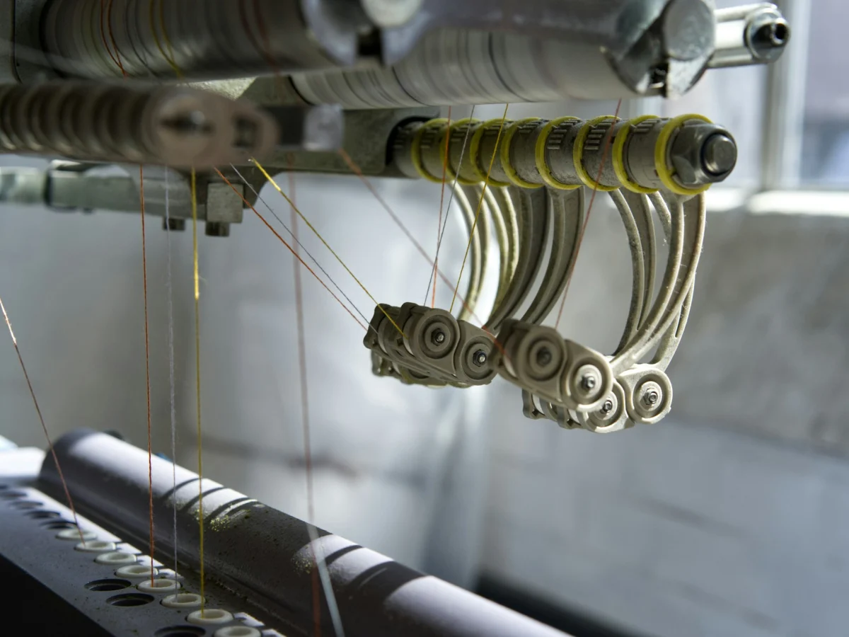
Yarn guides, a tensioning mechanism and rollers in a textile machine
Yarn feeding and mechanical line layout in textile production.
07

From control board prototype to acceptance on the actual machine

Power supplies, sensor inputs, counters, communication and output behaviour are bench-tested on the first board. Subsequent trials use the actual machine, cables and material. Relevant conditions such as yarn or fabric type, different operating settings, sensor contamination, power loss and restarting are included in the acceptance checklist prepared with the manufacturer.

Connection and configuration records are prepared for the accepted version, and a production test is planned for every board. We provide prototype PCB manufacturing and assembly only for customer projects developed by VOMRO, as part of prototyping and production preparation. The design revision, bill of materials and software version are matched within the same delivery package.

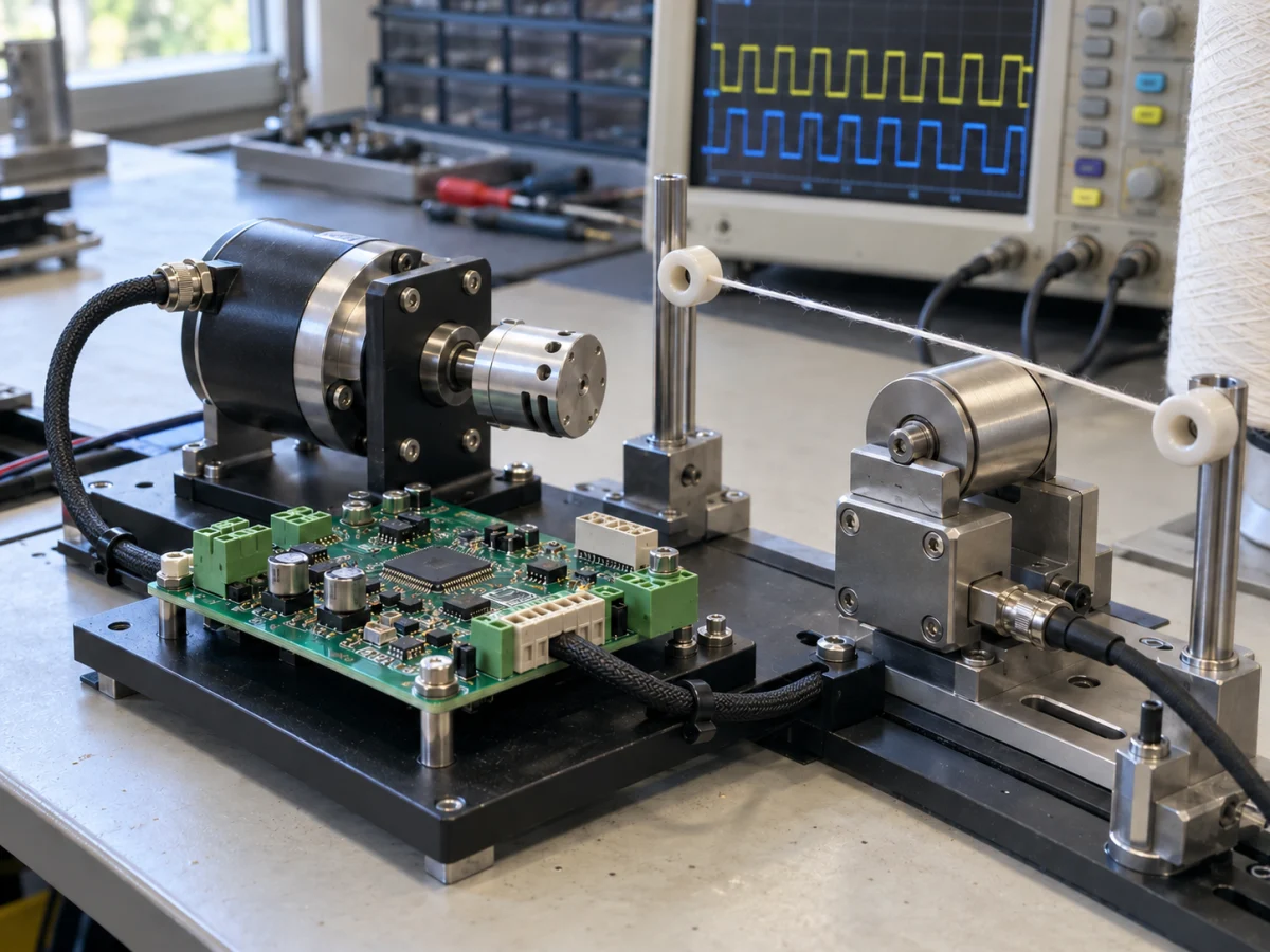
Textile control board prototype tested with yarn guides and rotary sensors
Representative application image.
08

A project for your brand with usable source files

For the first discussion, simply share what your machine does, its existing boards and drives, the function you want to change and the available model options. At your request, we complete a non-disclosure agreement (NDA) before technical drawings and detailed files are shared. The development scope is defined using existing design documentation and usage rights.

At project completion, we deliver the source code, schematic and PCB design files, production outputs, in-scope mechanical CAD and technical documents we have developed. File formats, acceptance criteria and the deliverables list are clarified at the outset. Version, test and programming information the manufacturer will need for later model or service revisions is included in the package.

How it works

A clear process from start to delivery.

Not every project looks the same; however, the measurable requirement, controlled revision, and field verification steps remain unchanged.

  1. 01

    We define the machine

    Together, we define the material flow, sensors, units to retain and new functions.

  2. 02

    Develop the board and software

    We develop the electronics, user display, communication and mechanical layout against shared requirements.

  3. 03

    We validate the prototype

    We assess bench and actual-machine trials against the manufacturer's acceptance checklist.

  4. 04

    We hand over the source files

    We deliver the approved version's design, software, production and test records.

Frequently asked questions

Before starting the project

The technical scope, deliverables and test plan are clarified together according to the requirements of your project.

Which textile machines can you develop custom electronics for?

Applications such as yarn transfer and winding, length counting, fabric feeding, auxiliary sampling equipment and process monitoring can be evaluated. A scope is prepared for the entire machine or a specific measurement and control module.

Can we retain the existing PLC or motor drive?

Yes. After reviewing the documentation and accessible interfaces, a custom board can be developed to work with the existing control architecture. The new board's roles, commands and feedback are defined alongside the systems to be retained.

Can we use the same control board in different machine models?

An architecture for a model family can be created by defining shared and varying functions at the outset. Inputs, drives, displays and connection options are evaluated, while model settings and board revisions are managed together.

Can yarn break and length data be transferred to central software?

With suitable sensors and interfaces, these events can be recorded and transferred to a local display or central system. Event meanings, timestamps and recording behaviour during connection loss are included in the project scope.

What information should we prepare for a quotation?

You can share a summary of machine operation, a sensor and drive list, existing connection documents, the intended new functions and production expectations. These are reviewed alongside the operating environment and acceptance conditions to prepare the development scope.

How do you handle an NDA and source file delivery at project completion?

At your request, we complete the NDA process before detailed information is shared. We deliver the source code, electronic and mechanical design files and technical documents developed within the project according to the deliverables list agreed at the outset.

Let's start with your idea

Let's talk about the product you dream of and the need you want to solve.