
Technical decision guide · OEM machine development

Custom control boards for machine manufacturers: from design to production testing

Developing a control board for a repeat-produced machine family involves more than getting the first prototype running. Signal types, software behaviour, variants, sourcing, testing and servicing all inform the same design decisions. This guide helps OEM machine manufacturers define a custom electronics project from the pre-quotation stage through to delivery of production files.

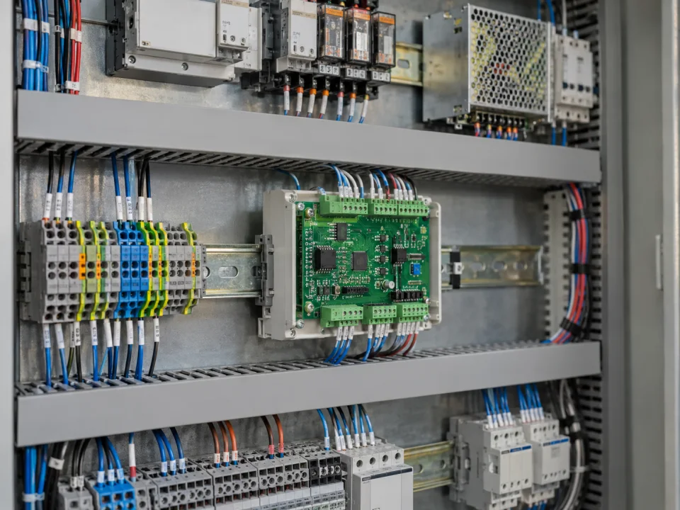
Representative application of the electronic board built into the electrical control panel for the machine control system
Representative application image.
DecisionPLC, auxiliary board or custom control
basic inputI/O and machine status list
OutputVerified design and technical files

VOMRO engineering approach

The value of the machine board is revealed in subsequent productions as well as in the first sample.

How to install electronic control on a new packaging, dosing, fixture or special process machine is a decision that should be made early. An off-the-shelf PLC, auxiliary I/O board and machine-specific controller impose different development burdens. How often the function repeats, the operator's need for adjustment, and the manufacturer's service organization change these options. Units used in the same assessment should have equal coverage; It is misleading to compare a bare PCB price to a complete electrical control panel solution.

The framework below prepares a project by defining control responsibilities, electrical interfaces and acceptance methods; it is not a component selection list. Numerical ranges illustrate interface types, while the project's actual limits depend on sensors, loads and machine conditions. The objective is a design the customer can use and test on their own machine and receive together with its technical files.

01

1. Distinguish the roles of the PLC, auxiliary I/O board and custom controller

It is not necessary to develop a special board if the ready-made module meets the need. Frequently changing site logic and existing maintenance ecosystem may support the selection of PLC. An auxiliary board for dedicated sensor measurement, pulse processing or protocol conversion can be used on the same machine. When a repeated, limited control function needs to be collected in a single unit, a more comprehensive custom controller is evaluated.

A custom board is not always cheaper or faster. It brings initial development, testing and ongoing maintenance responsibilities. The expected unit quantity across the machine family, model differences and sourcing plan affect whether that effort pays off. Document the division of responsibilities between the main control system, motion drives and safety functions. The system's response to board failure or communication loss must be part of the architecture decision.

  • Clearly describe the function missing from the ready-made solution
  • Evaluate the quantity of repeat units, variants and maintenance team
  • Define control and safety responsibilities separately
02

2. Don't limit the I/O list to just the number of channels

For every input, specify the sensor model, supply, electrical type, range and timing requirement. A 24 V PNP/NPN digital input differs from a 0–10 V or 4–20 mA measurement circuit. Current-loop design examines sensor power and the complete connection conditions; voltage measurement examines input range and source characteristics. Encoders require channel structure, output level, frequency and cable information.

Specify the type and current of the load on the outputs, such as relay, valve, lamp or driver input. Switching frequency and initial power-up state are also design inputs. Determine target accuracy and verification points for analog measurement and shortest event time for pulse inputs. If the connector pinout and wiring harness are part of the same document, the mechanical team and integrator can work from the same connection definition.

  • Channel name, type, range, unit and cable information
  • Output load, current and initial state
  • Measurement accuracy, timing and verification method
03

3. Consider the 24V supply and machine environment in their actual conditions

Nominal supply value does not describe the entire electrical environment. The machine's startup sequence, valve and relay loads, supply drop, effect of motors and earth connections of different units should be examined. The necessary protection, filtering and insulation are designed according to these conditions. The presence of sensor supply and precise measurement on the same board also affects placement and return current decisions.

The board's reset and startup behaviour are validated together with the software. Requirements define how accidental output activation is prevented before the supply is adequate, how outages affect parameter storage and how operation resumes when power returns. Cabinet installation checks cover heat, airflow, service access and connection distances. Laboratory functional testing and the intended environmental and electrical validation are separate activities; the scope and responsibility for external testing are planned separately.

  • Supply variations, startup and power loss
  • Grounding, insulation and cable effects
  • Thermal layout, service and external test plan
04

4. Document the meaning of the messages for Modbus or CAN

RS485 is the electrical connection layer; Modbus brings the definition of messages and operations. Addressing, register map and data types must be defined, along with the line's topology, termination and isolation needs. The scale at which a temperature is moved, the order of multi-byte fields, and how the invalid value is represented can be critical in integration. Official Modbus sources treat the application protocol and serial line manual as separate documents.

Physical compatibility alone is also insufficient for CAN: the application protocol, message identifiers and cycle behaviour must be defined. Permissions, timeouts and result reporting are specified for each command. If a repeated start command must not create a second operation, the software is designed accordingly. The data dictionary must be a deliverable that lets the PLC or server team understand the interface without the physical device.

  • Physical network drawing and separate message dictionary
  • Unit, scale, address and read/write permissions
  • Timeouts, retries and command results
05

5. Define machine states, parameters and model variants

Specify which events change states such as startup, ready, running, waiting, fault and service. An operator stop, missing sensor input and communication loss need not produce the same response. Clarify whether recipe or parameter changes apply during the current cycle or at the next start. Range checks for stored values and restoration of defaults are also software requirements.

If the same board will be used across different machine models, the configuration selection method is defined. Loading settings for the wrong model must be detectable. Board revision, software version and machine configuration are kept together in service records. Field updates require programming access, authorisation and version compatibility to be considered from the outset. A clear table manages truly shared and differing functions, avoiding unnecessary proliferation of variants.

  • State transitions and post-error restarts
  • Parameter ranges, recording and execution time
  • Model compatibility with hardware/software version
06

6. Plan the BOM and production testing from the first board design

The bill of materials (BOM) must include not only the short name of the component but also its defined features and manufacturer's parts information. The supply status and alternatives of critical parts are reviewed. A substitute change may create electrical, mechanical or software effects; It is not considered equivalent without verification of suitability. Board layout is evaluated along with connector access, assembly, programming and test fixture.

Checks required for every manufactured board are distinguished from comprehensive design validation tests. Supply current, I/O channels, communication and version checks are made repeatable. Recording test results against the board identity supports later service diagnostics. VOMRO's prototype PCB fabrication and assembly support is provided only within customer projects it develops. Pilot production findings are incorporated into the final file revision.

  • BOM with manufacturer part details and verified alternatives
  • Accessible test points for programming and fixtures
  • Production control result associated with board ID
07

7. Do prototype acceptance with machine scenarios

Write a verification method against each core requirement. Analog input can be tested with specific reference points, pulse input can be tested with defined frequencies, and communication can be tested with correct and incorrect messages. The expected outcome for sensor breakage, power failure and command repetition should be clearly stated. The hardware revision tested, software version and equipment used are recorded.

The pilot machine reveals cable-routing, operator-interaction and real-load behaviour that bench tests miss. Findings become a change list identifying the revision in which each correction is included. One successful cycle does not prove every operating condition. Production should not be approved until the scoped acceptance scenarios are complete. Access to the machine, actual sensors and the customer's process information must be included in the pilot schedule.

  • Matching requirement, test condition and expected result
  • Trial on real sensor, load and pilot machine
  • Findings and acceptance records closed with revision
08

8. Document source file delivery and the project kickoff package

However, getting a production output is not the same as getting an editable design source. EDA schematic/PCB resources, mechanical CAD resources, BOM, production files, embedded software resources and technical documents belonging to the project should be clearly included in the delivery list. The compilation environment, programming steps, interface definition, and testing methods are also required for reuse. License terms for third-party tools and components are stated separately.

At VOMRO, an NDA can be signed at your request before technical details are shared; project source code, design files and technical documentation are delivered at completion. For the first meeting, prepare the machine function, I/O list, power supply, communication, space limits and target quantity. Missing technical details are resolved during requirements work. A clear scope and acceptance list turn the quotation into a comparable project proposal that can be assessed technically.

For new functions requested after the project starts, we review the hardware, software and retesting required. The effects on cost, schedule and the deliverables list are clarified separately before implementation.

  • Editable EDA/CAD and software sources
  • Production, interface, programming and test documentation
  • Project starting with NDA, deliverable list and scope
Compare machine control architecture by need
ApproachWhen is it evaluated?Major decision
PLC and ready-made modulesIf standard function and existing maintenance ecosystem are suitableScope of expansion, electrical control panel and commissioning
Auxiliary board alongside a PLCIf there is a special sensor, I/O or communication taskInterface boundaries and division of responsibilities
Machine specific controllerIf repeated, defined control function is to be integratedDevelopment, production testing and life cycle

How it works

Turn decisions into a project plan.

Not every project looks the same; however, the measurable requirement, controlled revision, and field verification steps remain unchanged.

  1. 01

    Choose architecture

    Compare off-the-shelf control, auxiliary board and custom controller options against the same scope.

  2. 02

    Document the interfaces

    Bring I/O, power supply, protocol, mechanical requirements and machine states together in one requirements list.

  3. 03

    Verify with pilot

    Implement acceptance scenarios with real machines, sensors and loads.

  4. 04

    Get the tech pack

    Check the source, production, interface and test files of the approved revision against the submission list.

Frequently asked questions

Before starting the project

The technical scope, deliverables and test plan are clarified together according to the requirements of your project.

Is a custom machine control board always more economical than a PLC?

No. Quantity, reuse, development and testing labor, assembly and maintenance are evaluated together. The comparison must be made with the same functionality and scope of delivery.

Can we connect PNP and NPN sensors to a single input?

That depends on the input circuit. Sensor and connection types are specified at the outset; one input is not assumed to support both types. The required options are addressed in the electrical design.

Why should production testing be decided at the initial design?

Access to programming and measurement points affects board placement. If checks are considered late, fixture, assembly or board revision may be required. Production testing aims to re-verify the basic functionality of each unit.

Are Gerber files sufficient for source design delivery?

Manufacturing outputs such as Gerber files do not replace editable schematic and PCB source files. VOMRO delivers the relevant design source files and technical documentation at project completion, with formats agreed at the outset.

Which costs are shown separately in a custom control board quote?

Circuit and PCB design, embedded software, prototyping and validation fall within the development scope. Component, fabrication, assembly, programming and testing costs for subsequent boards are assessed separately. If a test fixture, mechanical part or external laboratory work is needed, its scope is also specified in the quote. Quotes should be compared using the same deliverables list and production quantity.

What determines the schedule from the first prototype to production?

The clarity of requirements, component procurement, prototype production, software scope and access to the machine for pilot trials affect the schedule. The first working prototype and a production-ready revision are separate stages; test findings and necessary corrections are also included in the plan. Rather than specifying a fixed number of weeks or a delivery date before a technical review, we define the stages and the inputs needed from the customer together.

Your project, your product

Developed confidentially and delivered with source files.

We may work with a confidentiality agreement (NDA) before sharing technical details. At the end of the project, we deliver the source codes, design files and technical documents we have developed to you.

  • NDA before sharing technical information
  • Clear deliverables agreed at the outset
  • Source and technical files at the end of the project
Our confidentiality and delivery process
Let's start with your idea

Let's define the scope of a custom control board for your machine.

Tell us what the machine does, its existing control setup and your estimated production quantity. In the initial discussion, we can identify missing technical information and the work needed to prepare a quote.