
Technical decision guide · Agricultural machinery integration

CAN bus, J1939 and ISOBUS integration for agricultural machinery

The answer to 'The machine has CAN; can we access its data?' depends on more than the connector. Physical connectivity, message meaning, data access permissions and the intended function must be assessed separately. This guide helps define distinct scopes for reading data, controlling implements and integrating an ISOBUS terminal in an agricultural machinery project.

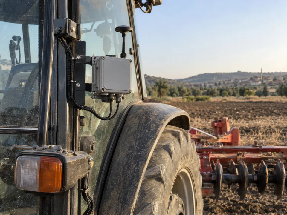
Representative application of tractor-mounted electronic device to collect data from agricultural machinery
Representative application image.
PreconditionModel, interface and data document
DistinctionData reading and control command
VerificationBench + terminal + field

VOMRO engineering approach

Just because the link works doesn't mean the target function is complete.

A gateway receiving messages from the machine network is only the first technical step. We must also verify the physical quantity each message represents, whether it is current and how it will be used in reports. Engine speed and an implement's distributor shaft speed, for example, are different measurements. Even when tractor speed is accessible, its source and low-speed behaviour can affect application-rate calculations. A signal's context of use is as much a requirement as its name.

Make the integration request concrete through four outputs: data to receive or produce, machines to connect, functions the operator will see and results to demonstrate during acceptance testing. Make, model year, terminal version and ECU configuration belong in this definition. Without them, 'work on every tractor' is not an engineering scope. An initial review identifies uncertainty in data access and protocol compatibility before prototyping.

01

1. Distinguish the CAN bus connection from the message dictionary

CiA's description distinguishes the lower CAN layers from higher-level protocols such as J1939. The CAN cable, transceiver and controller provide the communication infrastructure; the application definition determines whether a message byte represents temperature or status. Different message dictionaries can use the same physical interface. Knowing the CAN-H and CAN-L connections alone is therefore insufficient to interpret machine data.

The initial review establishes connector pinout, power supply, bit rate, topology, termination and the permitted connection point. We assess the electrical loading and cable branch of any device added to the existing machine network. Support for CAN Classic and CAN FD is not assumed across devices. Gateway hardware is selected for the relevant network conditions; a short laboratory cable does not represent the long cables and electrical noise of the machine.

02

2. Define PGN, SPN and signal validity for J1939

In J1939 projects, a PGN (Parameter Group Number) identifies a parameter group and an SPN (Suspect Parameter Number) identifies a defined parameter. SAE's J1939 Digital Annex is one official reference for these definitions. Decoding a signal requires more than its number: position, length, resolution, offset, unit and invalid-value representations in the data field must also be known. Document version and access licensing are checked at the start of the project.

We do not assume every requested value is broadcast by every machine. Each required signal is checked for transmission frequency, source and whether it arrives on request or automatically. Source-address changes, data timeouts and address management inform the software architecture. If an expected message does not arrive, the system reports validity rather than presenting the last value indefinitely as current. Manufacturer-specific messages require authorised documentation or data definitions with appropriate usage rights.

03

3. Define the ISOBUS objective as a function, rather than simply asking for compatibility

ISOBUS covers agricultural machinery and implement communication associated with ISO 11783. AEF explains that interoperability depends on the functions the components support in common. Two products labelled ISOBUS therefore cannot be assumed to support every feature together. The project records the tractor, terminal and implement roles and their software versions, and identifies which component provides each required function.

UT concerns the implement interface on the operator terminal; TC-BAS covers task data documentation; TC-GEO covers position-dependent data and variable rate; TC-SC covers section control. These functions are not interchangeable. An interface appearing on the terminal does not establish that automatic section control is complete. The protocol stack, licence, object pool and test infrastructure are assessed against the objective. AEF conformity and certification are planned separately; neither certification nor compatibility with every brand is promised without assessment.

04

4. Treat read-only data access and control commands as separate work packages

A data-monitoring project may be limited to reading and recording permitted signals. If passive monitoring is required, we verify that the hardware and driver support a true listen-only mode, distinguishing it from acknowledgement behaviour during normal CAN participation. If a request message must be sent to obtain a signal, that operation also belongs in the defined data-access scope. 'Read only' does not remove the need to examine network behaviour.

In a system that generates control commands, operator authority, validity period of the command, feedback and behavior in case of communication loss are determined. The control screen sending the command and the mechanical operation taking place are different events. Situations such as applying the old command on reconnection are evaluated. The tractor's main braking or steering functions and automatic steering require different risk and verification than an auxiliary data collection project; This guide does not claim certified solution competence in these areas.

05

5. Map out the responsibilities of the ECU, sensors, HMI and gateway

In a planting equipment, the sensor board can measure seed passage, the equipment ECU can execute its operating logic, HMI can indicate the status to the operator, and the gateway can transport the records to the server. Whether these are on a single board or in separate units is a project decision. System boundaries become clear when the data owner, unit, update time and error behavior are written for each connection. For example, an explicit requirement would be whether internet loss would halt local control.

A 4G/GNSS unit can record measurement time separately from server arrival time. We define how invalid position data is marked, offline storage capacity and retransmission behaviour. If an existing manufacturer platform must be connected, an authorised API may be considered instead of the physical machine network. Deere's equipment interface, for example, ties access to organisations and permissions; this does not establish equivalent access for other brands or every data item.

06

6. Check the manufacturer's documentation, DBC and data rights first.

For the project, the current machine manufacturer's connection and message documents, service access method and the scope of use it allows are requested. If there is a signal definition file such as DBC, the source, version and usage rights of the file are recorded. Being able to access a file does not mean permission to redistribute or unrestricted transfer to the client. Since raw CAN records may also contain customer, machine and operating information, the scope of sharing must be determined.

An NDA governs confidential sharing of technical information during cooperation. At project completion, VOMRO delivers the source code, schematics, PCB designs, mechanical CAD and technical documentation it develops. Licence terms for third-party protocol stacks, standards documents and manufacturer message dictionaries are stated separately. The handover package must identify project-owned files, files requiring additional access and the build environment. Development is not treated as complete while data access remains unresolved.

07

7. Link bench, simulation and field testing

On the test bench, a setup generating known signals checks decoding, unit conversion and timeouts. Replaying recorded messages allows comparison of normal and missing-data scenarios, but does not reproduce the actual machine's electrical and mechanical conditions. Simulated sensors, actual loads and the target terminal are distinct test inputs. Each result must record hardware revision, software version, message definitions and test conditions.

The pilot machine is checked against expected outcomes for supply changes, disconnections, ECU restarts and relevant sensor faults. ISOBUS projects test the target terminal and implement combinations separately; any required conformity process is scoped independently. We track which software version resolves each field issue. VOMRO's prototype PCB manufacturing and assembly support form part of this prototyping and verification process only for customer projects developed by VOMRO.

08

8. Prepare the project specification with a concrete example

Sample draft: "A separate flow sensor will be read with the allowed speed data on the tractor and spraying equipment specified by the customer; the target and measured value will be shown on the operator screen; work records will be stored when there is no internet and transferred to the server during the connection." This is a scope writing example, not a client testimonial. In the first stage, the project boundary is drawn by clearly stating that no control command will be sent to the machine or which control will be added.

Machine brand/model/year, terminal and ECU versions, sensor data sheets, pin connection, message document and access authorization are added to the draft. Then the acceptance conditions are filled in: measurement range, allowable error, data delay, recording capacity and expected behavior on interruption. Numerical targets are determined together depending on the field. The delivery list includes source code, PCB/CAD, wiring diagram, build information, test report, and third-party license list. Thus, the proposal can be evaluated on the same functionality and the same validation expectation.

  • Requested data: source, unit, frequency and validity
  • Machine scope: model, version, terminal and authorized document
  • Acceptance: measurement, delay, interruption and field testing
  • Delivery: source, design, connection, testing and license list
Distinguishing the project scope for CAN bus, J1939 and ISOBUS
TitleWhat does it provide?What does it not show on its own?To be verified in the project
CAN infrastructureSublayers for message transmission with compatible hardwareThe meaning of a message or an ISOBUS functionPin, line speed, topology, termination and electrical conditions
J1939 data integrationData processing via defined parameter groups and signalsThat every machine broadcasts all the required dataPGN/SPN definitions, data source, timeout and authorised access
ISOBUS function integrationStandards-based structure for targeted terminal and equipment functionsThat all features or certification are already available for every brandTarget function, software stack, license and actual combination testing
4G/API telemetrySharing authorized data with software outside the machineThat local control or access to machine data is automatically providedData permissions, coverage, local recording, authentication and synchronisation

How it works

Turn decisions into a project plan.

Not every project looks the same; however, the measurable requirement, controlled revision, and field verification steps remain unchanged.

  1. 01

    Write the function

    Specify data readout, operator display and control request separately.

  2. 02

    Verify access

    Review the machine list, manufacturer's documentation and permitted signals.

  3. 03

    Describe the test

    Define acceptance criteria for bench testing, the target terminal and the pilot machine.

  4. 04

    Clarify delivery

    Define the source files, designs, versions, test reports and licence list to be delivered.

Frequently asked questions

Before starting the project

The technical scope, deliverables and test plan are clarified together according to the requirements of your project.

Can all sensor data be read from an agricultural machine with CAN bus?

No such guarantee can be given. The relevant data may not be available on the line, may come from a different ECU, or may require manufacturer-specific definition. Accessible signals are determined by examining the brand, model, configuration and authorized message document.

Are J1939 and ISOBUS the same thing?

No. They can be included as related technologies in the same project; target data definitions and agricultural terminal/equipment functions are separate. It is not enough to define the scope only through the protocol name without writing down which function is desired.

Is displaying an interface on an ISOBUS screen sufficient for section control?

No. Displaying an interface and performing section control are separate terminal functions. Support for the requested function in the terminal and implement, required position and data inputs, and interoperability tests must also be evaluated.

Which files should we prepare before the project proposal?

A good start is the list of machines and terminals, desired signals, current connection information, sensor data sheets and the protocol documents you are entitled to use. Confidential details may be shared after NDA; For missing information, a preliminary technical review can be made first.

Your project, your product

Developed confidentially and delivered with source files.

We may work with a confidentiality agreement (NDA) before sharing technical details. At the end of the project, we deliver the source codes, design files and technical documents we have developed to you.

  • NDA before sharing technical information
  • Clear deliverables agreed at the outset
  • Source and technical files at the end of the project
Our confidentiality and delivery process
Let's start with your idea

Let's talk about the product you dream of and the need you want to solve.