
Device development specific to the equipment manufacturer

Custom electronics development for livestock and farm equipment

You may wish to develop milking equipment, a feeding unit, a calf feeder or a poultry house control module. VOMRO designs the custom circuit board, sensor interfaces, user display, device software and mechanical layout together, around the manufacturer's operating workflow.

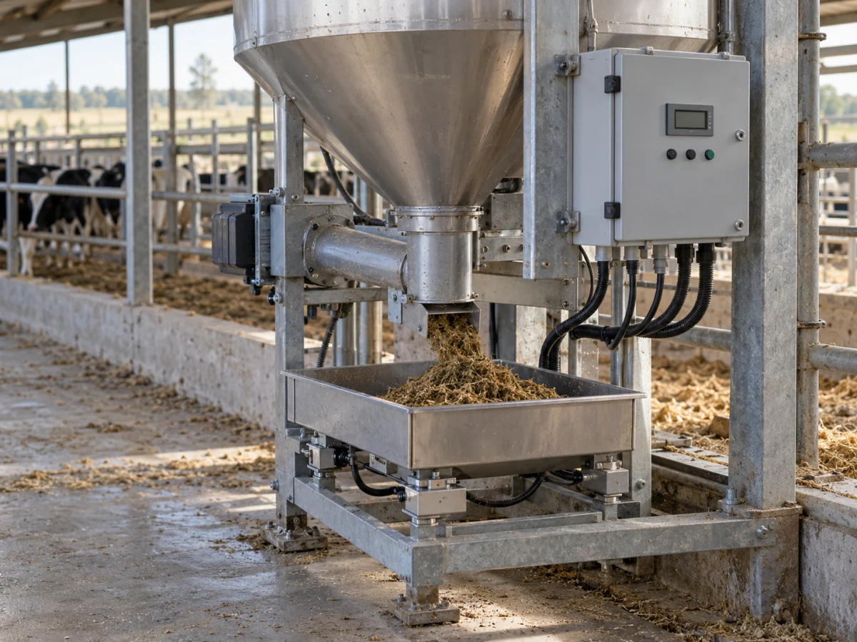
Weighing tray, drive mechanism and enclosed electronic control box in farm feeding equipment
Representative application image.
CustomerFarm equipment and device manufacturers
IntegrityOperating sequence, sensors and device records
DeliverySource code, design and technical files

Your project, your product

Developed confidentially and delivered with source files.

We may work with a confidentiality agreement (NDA) before sharing technical details. At the end of the project, we deliver the source codes, design files and technical documents we have developed to you.

  • NDA before sharing technical information
  • Clear deliverables agreed at the outset
  • Source and technical files at the end of the project
Our confidentiality and delivery process

VOMRO engineering approach

We turn everyday farm operations into manufacturable device designs.

Dispensing feed, reading an identifier, measuring flow and logging an operation are related but separate tasks. We begin farm equipment control board design by defining their sequence. The user's action, the machine's physical result and the software record are considered together within the same product.

We can develop a new OEM device, a control module for existing equipment or shared electronics for different models. Milking support systems, feed preparation and distribution equipment, identification reader interfaces, milk tank data monitoring and poultry house environmental monitoring are each addressed according to their needs. We define acceptance conditions with the manufacturer and establish a concrete electronics, mechanical and software scope.

01

Defining operating sequences for milking and feeding equipment

A device's preparation, start, operation, stop and cleaning states are defined around the manufacturer's process requirements. Sensors monitored in auxiliary milking control differ from the portioning and operating steps of a calf feeding unit. At the outset, we distinguish which units the board controls and which information it only monitors.

We plan what the operator sees if an operation is interrupted, the restart sequence and the conditions for completing its record. Local controls, the display and service access follow the same workflow. Prepared using the manufacturer's equipment knowledge, this state list forms the basis of embedded software and subsequent acceptance trials.
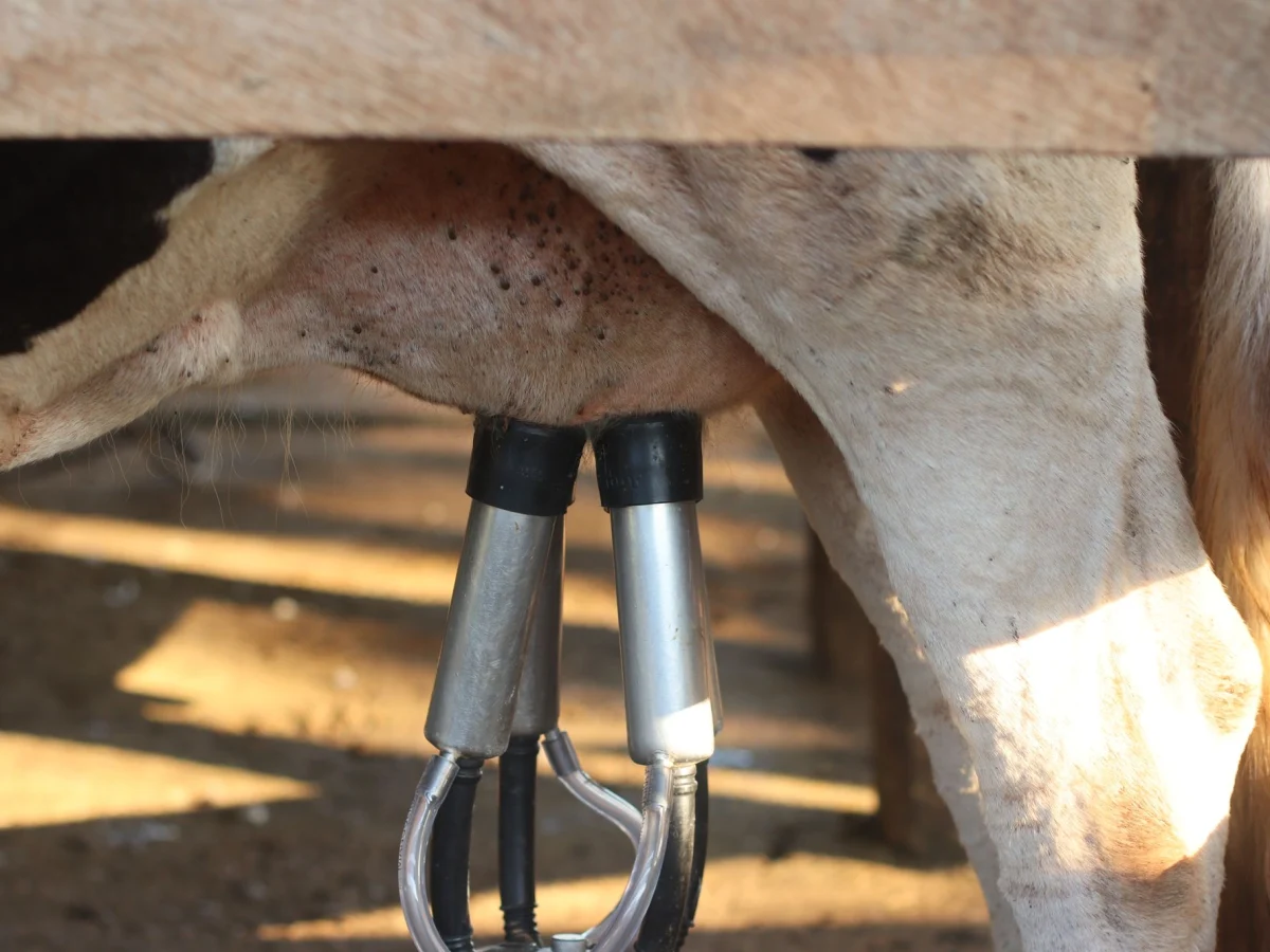
Stainless steel milking cups fitted to a dairy cow and connected hoses
Milking clusters and milk line connections in a milking application.
02

Relating feeding, weighing and flow information to the actual process

Running a motor for a set time and measuring the amount of feed dispensed are different methods. Depending on the product, a load cell, flow meter, level signal or position sensor is considered. Since hopper mechanics, material flow and vibration affect measurement behaviour, electronics are selected alongside the actual assembly.

For a feed dosing control board, the target quantity, measured result, waiting and completion conditions are defined. Jams, an empty hopper and invalid sensor data are logged separately. Following dry prototype trials, comparisons are made using actual feed or liquid; required settings and acceptance limits are established around the manufacturer's product targets.

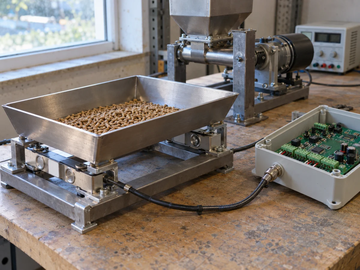
Prototype test setup with a feeding mechanism, collection tray and control board
Representative application image.
03

Managing identification and operation records within the same device workflow

An RFID reader or existing identification unit can be integrated into the equipment's operating sequence through an interface. The reader, tag type, reading area and protocol are selected alongside the existing hardware. The point at which an identifier is read, repeated reads of the same identifier and a connection loss before an operation starts are evaluated in the actual device layout.

Identification records can be associated with the operation time, device used, target setting and actual measurement. Responsibilities are divided between local processing and the central data system. The operation shown on the operator display and the record sent to the server share the same transaction identifier; behaviour is defined to prevent repeated transmission from creating a second transaction.

04

Environmental data and auxiliary control for poultry house and barn equipment

Poultry house temperature and humidity monitoring, barn fan or lighting status and milk tank temperature logging can be addressed as separate modules. Measurement points, sensor protection, cabling and the decisions supported by the data are defined. The distinction between a data acquisition device and a control module that operates a load is kept clear.

The local display, threshold settings and notifications are developed around the farm's operating arrangements. They are based on the operating values defined by the manufacturer and acceptance conditions set by relevant specialists. If data must be transferred to an existing environmental control system, accessible protocols and commands are reviewed; measurements and equipment behaviour are monitored together during field trials.

05

Defined local operation and traceable records even when disconnected

Whether the equipment's everyday functions depend on internet connectivity is a product decision. Steps that must run locally, events to log and settings that may be changed remotely are defined at the outset. Wired communication or an appropriate wireless connection is selected according to the facility layout and existing infrastructure.

While disconnected, records can be stored with time and device information; transmission order and retries are managed after reconnection. Settings and the status of interrupted operations are checked after a power outage. User notifications and conditions requiring service intervention are clearly distinguished on the display. These workflows are included in prototype acceptance trials.

06

Mechanical layout suited to cleaning, humidity, power and cabling conditions

Washing methods, possible liquid contact, condensation, dust and cleaning agents are important inputs to enclosure selection. The electronics compartment, sensor connections and user-facing surface are designed together. Gaskets, cable entries and the service cover are examined in the actual mounting location, and the intended protection conditions are included in the validation plan.

Power and driver interfaces for loads such as pumps, motors and valves are defined from their electrical characteristics. Cable lengths, connection orientations, mechanical fixing and replaceable service units are planned. In addition to bench tests, restarting, connection and maintenance steps on the actual equipment are evaluated and incorporated into design revisions.

07

From bench prototype to the manufacturer's pilot equipment

Initial board trials validate power, sensor readings, outputs, the display and communication separately. The next stage runs an integrated operation with the mechanism and actual material. Depending on the project, the manufacturer's acceptance checklist may include the dispensed quantity, record creation, sensor faults, stopping, behaviour after interruptions and maintenance steps.

Records obtained from pilot equipment are associated with the approved design and software version. Programming, settings loading and production test procedures are prepared for boards entering repeat production. We provide prototype PCB manufacturing and assembly only for customer projects developed by VOMRO. This work is planned as part of product development and preparation for production.

08

A project for your own brand, confidentiality and technical continuity

In the first discussion, you can describe the equipment you want to manufacture, its operating steps, sensors and loads, existing mechanical arrangement and target model options. At your request, we complete a non-disclosure agreement (NDA) before technical details and drawings are shared. The scope defines what the first prototype will demonstrate and how it will be accepted.

At project completion, we deliver the source code, electronic and mechanical design files and technical documents we have developed. Schematic and PCB sources, production outputs, the bill of materials, connection information and in-scope installation and test records are specified in the deliverables list. Matched to the working version, this package provides a technical basis for subsequent model and maintenance developments.

How it works

A clear process from start to delivery.

Not every project looks the same; however, the measurable requirement, controlled revision, and field verification steps remain unchanged.

  1. 01

    Map the workflow

    We define the equipment's steps, sensors, loads and the manufacturer's acceptance targets.

  2. 02

    Design the device together

    We develop the board, software, user display and mechanical mounting within the same product scope.

  3. 03

    Evaluate the prototype and pilot

    We compare bench results with the actual mechanism, material and operating environment.

  4. 04

    Deliver the production and source package

    We deliver approved design, programming and test files with technical documentation.

Frequently asked questions

Before starting the project

The technical scope, deliverables and test plan are clarified together according to the requirements of your project.

Which livestock equipment can you develop projects for?

Feeding and calf feeding devices, auxiliary milking control, identification reader interfaces, milk tank data monitoring and poultry equipment control modules can be evaluated. Each product's operating sequence and acceptance conditions are defined with the manufacturer.

Can an existing load cell, flow meter or RFID reader be used?

The device's technical documentation, electrical interface and protocol are reviewed. Connections can be developed for suitable units; reading and recording behaviour is tested in the actual equipment layout and intended operating conditions.

Can the equipment operate without internet access?

Functions that must run locally can be defined separately in the project. Storing queued records, transferring them after reconnection and determining when remote settings are applied are developed around the product's workflow.

Can different types of farm equipment use a shared control board?

An architecture for a model family can be created by examining common input, output and display requirements. The effects of different motor, valve and sensor options on hardware and software are evaluated at the outset.

What information should we bring to the initial project discussion?

You can share the equipment's purpose, operating steps, materials, sensors and loads, existing drawings and production expectations. Environmental, cleaning and maintenance conditions also help define the initial scope.

Are an NDA and source file delivery included?

Yes. At your request, we complete the NDA process before detailed information is shared. At project completion, we deliver the source code, electronic and mechanical design files and technical documentation for the project we developed, according to the agreed deliverables list.

Let's start with your idea

Let's talk about the product you dream of and the need you want to solve.